
The following information is transferred from the original MEDTEQ website, originally posted around 2009
 This article provides some background for the design and test of IBP (Invasive Blood Pressure) monitoring function, as appropriate to assist in an evaluation to IEC 60601-2-34 (2000).
Key subjects include discussion on whether patient monitors can be tested using simulated signals, and how to deal with accuracy and frequency response tests.
Principle of operation
Sensors
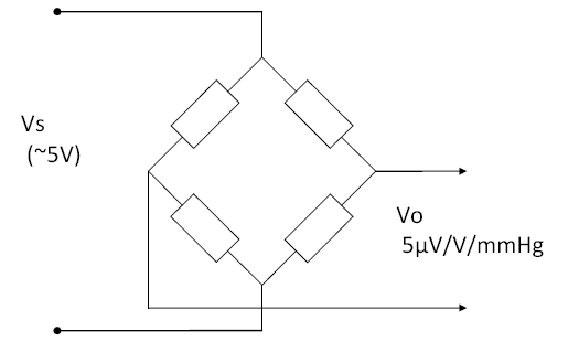 IBP sensors are a bridge type, usually adjusted to provide a sensitivity of 5µV/V/mmHg. This means the output changes by 5µV per 1 mmHg, for every 1V of supply. Since most sensors are supplies at 5V supply, this means they provide a nominal 25µV/mmHg. A step change of of 100mmHg, with a 5V supply, would provide an output of 2.5mV (5µV/V/mmHg x 5V x 100mmHg = 2.5mV).
The sensors are not perfectly linear, and start to display some significant "error" above 150mmHg. This error is typically around -1% to -2% at the extreme of 300mmHg (i.e. at full scale the output is slightly lower than expected). Some sensors have internal compensation for this error, and in many cases the manufacturers of patient monitors include some software compensation.
The sensors are temperature sensitive, although not greatly compared to the limits in IEC 60601-2-34. Tests indicate that over a temperature range of 15°C to 35°C the "zero drift" is typically less than 0.5mmHg, and gain variation less than 0.5%.
The sensors also exhibit variation of up to 0.3mmHg depending on orientation, so for accurate measurements they should be fixed on a plane.
Sensors well exceed the 10Hz frequency response limit in IEC 60601-2-34. Step response analysis (using a solenoid valve to release the pressure) found a rise time in the order to 1ms, and a frequency response of around 300-400Hz.
Equipment (patient monitor)
Most patient monitors use a nominal 5V supply to the sensor, but it is rarely exactly 5V. This does not influence the accuracy as most monitors use a ratio measurement, for example by making the supply to the sensor also the supply to the ADC (analogue to digital converter). When providing simulated signals (e.g. for performance testing of the monitor) the actual supply voltage should be measured and used for calculating the simulated signal. MEDTEQ's IBP simulator has a function to do this automatically.
The measurement circuit must be carefully designed as 1mmHg is only 25µV. A differential gain of around 300 is usually required to increase the voltage to a range suitable for ADC measurement, as well as a circuit to provide an offset which allows negative pressures to be measured. IBP systems always include a function to "zero" the sensor. This is required to eliminate residual offsets due to (a) the sensor, (b) measurement electronics and (c) the "head of water" in the fluid circuit. In practice, the head of water dominates this offset, since every 10cm of water represents around 7mmHg. Offsets associated with the sensor and electronics is usually <3mmHg.
Drift in offset and gain can be expected from electronic circuits, but assuming reasonable quality parts are used, the amount is negligible compared to the sensor. For example, between 15-35°C an AD620 differential amplifier (used in MEDTEQ's precision pressure measurement system) was found to have drift of less than 0.1mmHg, and a gain variation of less than 0.05%.
Because of the very low voltages involved, filtering and/or special sampling rates are often used to remove noise, particularly mains frequency noise (50/60Hz). This filtering and sampling is far more likely to impact the 10Hz frequency response requirement than the frequency response of the sensor.
Basics of pressure
The international unit of pressure is the Pascal, commonly seen as kPa or MPa, since 1Pa is a very small pressure. Due to the prior use of mercury columns to measure blood pressure, in medicine the use mmHg (millimeters of mercury) remains common for blood pressure. Many patient monitors can select either kPa or mmHg indication. The conversion between kPa and mmHg is not as straightforward as it might appear - whenever a liquid column is used to represent pressure (such as for mmHg), accurate conversion requires both temperature and gravity to be known. It turns out that "mmHg" commonly used in medicine is that at 0°C and "standard gravity".
 The use of the 0°C figure rather than room temperature might be the result of convenience: at this temperature the relationship is almost exactly 1kPa = 7.5mmHg, within 0.01% of the precise figure (7.500615613mmHg/kPa). This means easy conversion, for example 40kPa = 300mmHg.
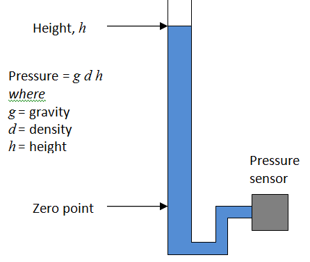
A water column can also be used as a highly accurate calibration source. To know the exact relationship between the height of water and pressure, you only need to know temperature to determine the density of water, and gravity at the site of measurement. After that, it is only a matter of using a simple relationship of P = gdh, although care is needed with units.
At 25°C, at Japan (Ise) the ratio for pure water to "standard" mmHg is 13.649mmH20/mmHg, or 136.5cm/100mmHg (contact MEDTEQ for more details on how to calculate this). Literature indicates that purity of the water is not critical and normal treated tap water in most modern cities will probably suffice. To be sure, pure or distilled water should be used, but efforts to find out just how pure the water would be overkill.
Testing to IEC 60601-2-34
IEC conumdrum: System test, or monitor only?
The IEC 60601 series has a major conflict with medical device regulations, in that they are written to test the whole system. In contrast, regulation supports the evaluation each component of a system as a seperate medical device. This reflects the practical reality of manufacturing and clinical use - many medical systems are constructed using parts from different manufacturers, where no individual manufacturer takes responsibility for the complete system, and patient safety is maintained through interface specifications.
The IBP function of a patient monitor is a good example of this, with specifications such as a sensitivity of 5µV/V/mmHg being industry standard. In addition, sensors are designed with high frequency response, and an insulation barrier to the fluid circuit. Together with the sensitivity, it allows the sensor to be used with a wide range of patient monitors (and the monitor with a wide range of sensors).
Thus, following the regulatory approach, standards should allow patient monitors and IBP sensors to be tested seperately. This would mean sensors are tested with true pressures, while patient monitors are tested with simulated signals, both using 5µV/V/mmHg interface specification. Accuracy and frequency response limits would be distributed to ensure an overall system specification is always met.
In fact, part of this approach already exists. In the USA, there is standard dedicated to IBP sensors (ANSI/AAMI BP 22), which has also largely been adopted for use in Japan (JIS T 3323:2008). This standard requires the accuracy of sensitivity to of ±1mmHg ±1% of reading up to 50mmHg, and ±3% of readings above 50 to 300mmHg. Among many tests, it also has tests for frequency response (200Hz), defibrillator protection and leakage current.
In principle, a sensor which complies with ANSI/AAMI BP 22 (herein referred to as BP 22) would be compatible with most patient monitors. Unfortunately, IEC has not followed up and the standard IEC 60601-2-34 is written for the system. Nevertheless, we can derive limits for accuracy for the patient monitor by using both standards:
|
Test point |
IEC 60601-2-34 limit (mmHg) |
BP 22 limit(mmHg) |
Effective patient monitor limit (mmHg) |
|
-45 |
±4 |
±1.5 |
±2.5 |
|
-30 |
±4 |
±1.3 |
±2.7 |
|
0 |
±4 |
±1 |
±3 |
|
30 |
±4 |
±1.3 |
±2.7 |
|
60 |
±4 |
±1.6 |
±2.4 |
|
150 |
±6 |
±4.5 |
±1.5 |
|
240 |
±9.6 |
±7.2 |
±2.4 |
|
300 |
±12 |
±9 |
±3 |
There are a few minor complications with this approach: the first is that patient monitors usually only display a resolution of 1mmHg. Ideally for the accuracy test, the manufacturer would enable a special mode which displays 0.1mmHg resolution, or the simulator can be adjusted in 0.1mmHg sets to find the change point. Second is that simulated signals should be accurate to around 0.3mmHg, or 0.1% full scale; this requires special equipment (MEDTEQ's IBP simulator has a compensated DAC output to provide this accuracy). Finally, many monitors compensate for sensor non-linearity, typically reading high around 200-300mmHg. This compensation improves accuracy, but could be close to or exceed the limits in the table above. Since virtually all sensors exhibit negative errors at high pressure, BP 22 should really be adjusted to limit positive errors above 100mmHg (e.g. change from ±3% to +2%, -3%), which in turn would allow patient monitors to have a greater positive error (+2%, or +6mmHg at 300mmHg), when tested with simulated signals.
Testing by simulation
In principle all of the performance and alarm tests in IEC 60601-2-34 can be performed using a similator, which can be constructed using a digital function generator and a simple voltage divider to produce voltages in the range of around -1mV to +8mV. For the tests in the standard, a combination of dc offset and sine wave is required.A digital function generator is recommended to provide ease of settings and adjustment.
As discussed above, the simulator should have an accuracy equivalent to ±0.3mmHg (±0.1% or ±7.5µV), which can be achieved by monitoring the output with a high accuracy digital mutlimeter. In addition, the output should be adjusted as appropriate for the actual sensor supply voltage; for example, if the sensor is 4.962V, the output should be based on 24.81µV/mmHg, not the nominal 25µV/mmHg.
MEDTEQ has developed a low cost IBP simulator which is designed specifically for testing to IEC 60601-2-34, and includes useful features such as automated measurement and adjustment for the supply voltage, and includes real biological waveforms as well as sine waves for more realistic testing .
Testing by real pressures
MEDTEQ has tested sensors against both IEC 60601-2-34 and ANSI/AAMI BP 22. For static pressures the test set up is only moderately complicated, with the main problem being creating stable pressures. For dynamic pressures, a system has been developed which provides a fast step change in pressure, to allow measurement of the sensor frequency response as described in BP 22 (although technical not using the 2Hz waveform required by the standard, the result is still the same). Test results normally show a response in excess of 300Hz (15% bandwidth).
Manufacturers have indicated that the mecahnical 10Hz set up required by IEC 60601-2-34 has severe complications, and practical set ups exhibit non-linearilty which affects the test result. Given that the sensors have demonstrated frequency response well above 200Hz, it is clear that patient monitors can be tested with a 10Hz simulated signal. Even for systems that can only be tested as a set, the test should be replaced by a step response test, which is simpler and more reproducable.
51.102.1 Sensitivity, repeatability, non-linearity, drift and hysteresis
(to be completed)