
Like EMC, CMRR testing is often considered somewhat of a black art in that the results are unpredictable and variable. This article attempts to clear up some of the issues by first looking at exactly how CMRR works in ECG applications and use of the RL drive to improve CMRR.
It also has a look at the importance of external noise, methods to eliminate and verify the set up is relatively free from external noise.
This application note is intended to support engineers that may already have some experience with CMRR testing but remained confused by variable results in individual set ups.

CMRR analysis from basics
CMRR is often considered a function of op-amp performance, but for the CMRR test in IEC/AAMI standards it turns out the indication on the ECG is mostly due to leakage currents passing through the 51k/47nF impedance.
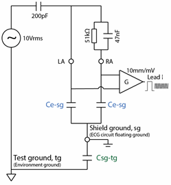
First, let’s consider the basic test circuit:

For those wondering why the circuit shows 10V and 200pF rather than 20V and 100pF divider found in circuit found in IEC/AAMI standards, this arrangement is the “Thevenin equivalent” and can be considered identical.
If this circuit was perfect, with the ECG inputs and gain element G floating with infinite input impedance, the 51k/47nF should have no effect and Lead I indication should be zero.
In practice, there will always be some small stray or deliberate capacitance in the system in the order 5 ~ 1000pF. This means the ECG inputs are not perfectly floating and small amounts of leakage will flow in the circuit.
The main cause of this leakage is the capacitance between each input and shield or ground of the floating ECG circuit, and between that ECG shield/ground and the test system ground.
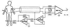
To understand how these influence the test it is best to re-arrange the circuit in a “long” fashion to appreciate the currents and current flow through the stray capacitance.
In this diagram, stray capacitance Ce-sg is added between the ECG electrode inputs and the ECG circuit ground (which is usually floating).
This capacitance is fairly high due to cable shielding and the internal electronics. Also each electrode has roughly the same stray capacitance. For example, a 12 lead diagnostic ECG measured around 600pF between RA and the shield, with a similar result for LA.
Capacitance Csg-tg between the ECG circuit ground (shield ground) and the test ground is also added.
This value can vary greatly, from as little as 5pF for a battery operated device with the cable well removed from the ground plane, to around 200pF for a mains operated device.
Lets assume Ce-sg are both 100pF, and Csg-tg is 10pF, and try to calculate the current that flows into the circuit. Although it looks complicated, it turns out the 51k/47nF is much smaller impedance compared to the stray capacitance, so as a first step we can ignore it. The total capacitance seen by the source is then a relatively simple parallel/series impedance calculation:
Ct = 1/(1/200+ 1/(100+100) + 1/10) = 9pF
We can see here that the largest impedance, in this case Csg-tg (shield to test ground), influences the result the most.

Next, we can calculate the total current flowing into the ECG:
I = 10Vrms x 2π x 50Hz x 9pF = 28nArms
This seems very tiny, but keep in mind ECGs work of very small voltages.
The trick here is to realise that because Ce-sg is similar for RA and LA, this current will split roughly equally into both leads; around 14nA in our example.

RA has the imbalance of 51kΩ/47nF which has an impedance of Z = 40kΩ at 50Hz. When the 14nA flows thought this it creates 0.56mVrms between RA and LA. This is measured normally and on a 10mm/mV results in around 8mm peak to peak on Lead I of the ECG display.
To summarize, the 10Vrms will cause a small but significant amount of leakage to flow into the ECG circuit. This leakage will split roughly the same into each electrode. Any imbalance in the impedance of each electrode will cause a voltage drop which is sensed as a normal voltage and displayed on the ECG as usual.
In the above example, we can see that the capacitance Csg-tg between the ECG shield and the test ground had the largest effect on the result. We assumed 10pF, but increasing this to just 13pF would be enough to change this to a fail result. Many devices have 100pF or more; and the value can be highly variable due to the position of the shielded cable with respect to ground.
With such a small amount of highly variable capacitance having such a big effect, how can ECGs ensure compliance in practice?
The right leg drive
Most ECGs use a “right leg drive”, which is active noise cancellation and is similar to the methods used by noise cancellation headphones. Although noise “cancellation” implies a simple -1 feedback, it is often implemented a medium gain negative feedback loop, and sometimes with shield also driven at the +1 gain.
Regardless of the method, the basic effect is to absorb the leakage current through the RL electrode, which prevents it from creating a voltage across any impedance imbalance (51k/47nF).
In reality these circuits are not perfect, and in particular it is necessary to include a reasonable size resistor in the RL to prevent high dc currents going to the patient especially in fault condition. This resistor degrades the CMRR performance.
The residual indication on most ECGs (usually 3-7mm) is mostly a measure of the imperfection of the RL drive. This will be different for every manufacturer, but generally repeatable. Two test labs testing the same device should get similar results. Two samples of the same device type (e.g. production line testing) should give roughly the same results.
Since each RL drive system is different it can no longer be predicted how the system will react to changes in the position of the cable with respect to the ground plane. Test experience indicates that most ECGs with a RL drive, the indication reduces if the cable is closer to the test ground (Csg-tg capacitance is increased). With normal set ups, the variation is not big. In an extreme case, a test with 12 lead diagnostic ECG a portion of the cable was tightly wrapped in foil and the foil connected to the test ground. In this case the displayed signal to reduced by about 40%.
It is recommended that the ECG cable is loosely gathered and kept completely over the ground plane. Small changes in the cable position should not have a big effect and not enough to change a Pass/Fail decision. In case of reference tests the cable position might be defined in the test plan.
Systems without A Right leg drive
In general, all mains operated ECGs will employ a RL drive as the leakage will be otherwise too high.
In battery operated systems, some manufacturers may decide not use a RL drive.
Without a RL drive the analysis shows the test result will be directly proportional to the leakage current and hence highly sensitive to the cable position with respect to the test ground. The result will increase if the ECG device and cables are closer to test ground plane. This has been confirmed by experiment where a battery operated test sample without RL drive was shown to vary greatly with the sample and leads position with respect to ground plane, with both pass and fail results possible.
With the advent of wireless medical monitoring, there may be battery operated equipment intended for monitoring or diagnostic applications, together with inexperienced manufacturers that may not know the importance of the RL drive. Current standards (-2-25, -2-27) are not written well since they do not define what is done with the cable.
If a RL drive is not used, the above analysis indicates the intended use should be limited to being always worn on the patient and tested similar to IEC 60601-2-47. If the device has long cables and the recorder may be situated away from the patient, an RL drive should be used to avoid trouble.
For ambulatory equipment, the standard IEC 60601-2-47 specifies that the cable is wrapped in foil and connected to the common mode voltage, not the test ground. This is assumed to simulate the cable being close to the patient. This is expected to improve the result, as leakage will be much lower. The test voltage for ambulatory is also much smaller, at 2.8Vrms compared to 20Vrms. As such ambulatory equipment may pass without a RL drive.
External noise
In the actual CMRR test set up, the ECG electrodes are floating with around 10-15MΩ impedance to ground. This high impedance makes the circuit very susceptible to external noise, far more than normal ECG testing. The noise can interfere with the true CMRR result.
Therefore for repeatable results, the test engineer must first set up to eliminate external noise as far as possible, and the test (verify) that there is no significant noise remaining.
To eliminate the noise the following steps should be taken:
- Place the equipment under test (EUT), all cabling and the CMRR test equipment on an earthed metal bench or ground plane (recommended at least 1mm thick)
- Connect the CMRR test equipment ground, EUT ground (if provided) and ground plane together and double check the connection using an ohm meter (should be <0.5Ω)
- During the test, any people standing near the set up should touch the ground plane (this is an important step, as people make good aerials at 50/60Hz).
To check the set up has no significant noise:
- Set up the equipment as normal, including the 20Vrms
- Set RA lead with impedance (51k/47n), check normal CMRR indication appears (usually 3-8mm)
- Turn the generator voltage off
- Verify the indication on Lead I or Lead II is essentially a flat line at 10mm/mV. A small amount of noise is acceptable (e.g. 1mm) as long as the final result has some margin to the limit.
If noise is still apparent, a ground plane over the cables may also help reduce the noise.
Typical Testing Results
Most indications for the 20V tests are in the range of 3-7mm. An indication that is lower or higher than this range may indicate there problem with the set up.
Indications are usually different for each lead which is expected due to the differences in the cable and trace layout in the test equipment, test set up and inside the equipment under test. Therefore, it is important to test all leads.
The 300mVdc offset usually has no effect on the result. However, the equipment has to be properly designed to achieve this result - enough head room in the internal amplifiers. So it is again important to perform the test at least for representative number of leads.
If the test environment is noisy, there may be "beating" between the test signal frequency (which is usually pretty accurate) and real mains frequency, which is not so accurate. This can be eliminated by taking special precautions with grounding and shielding for the test area. Solid metal benches (with the bench connected to the test system ground) often make the best set up.
And that 120dB CMRR claim?
Some ECG manufacturers will claim up to 120dB CMRR, a specification which is dubious based on experience with real ECG systems. The requirement in standards that use the 10V test is effectively a limit of 89dB (= 20 log (0.001 / (2√2 x 10)). A typical result is around 95dB. Although it might not seem much between 95dB and 120dB, in real numbers it is a factor of about 20.
It is likely that the claim is made with no imbalance impedance - as the analysis above shows, the imbalance creates the common mode indication, and without this imbalance most floating measurement systems will have no problem to provide high CMRR. Even so, in real numbers 120dB is a ratio of a million to 1, which makes it rather hard to measure. So the claim is at best misleading (due to the lack of any imbalance) and dubious, due to the lack of measurement resolution. Another challenge for standards writers?