
This article is copied from the original MEDTEQ website, originally published around 2009
~~~~~~~~~~~~~~~~~~~~~~~~~~~~~~~~~~~~~~~~~~~~~~~~~~~~~~~~~~~~~~~~~~~~~~~~~~
 Introduction
Defibrillator proof testing is common for equipment associated with patient monitoring, HF surgical (neutral electrode) and ECG, and any device that may remain attached to a patient during defibrillation. In order to speed up delivery of the defibrillator pulse, it is desirable to leave many of the applied parts connected to the patient; thus such applied parts should be able to withstand a pulse without causing an unacceptable risk. In general, a defibrillator proof specification is optional, however, particular standards may specify that it is mandatory (for example, ECG related).
This section covers the following topics related to defibrillator proof testing (defib testing):
Potential hazards / Defibrillator pulse characteristics / Design considerations / Practical testing / Test equipment calibration
Potential hazards
The potential hazards associated with the use of a defibrillator when other equipment is connected to the patient are:
- permanent damage of medical equipment attached to the patient
- loss of critical data, settings, operation for monitoring equipment attached to the patient
- inability of monitoring equipment to operate to determine the status of the patient (after defibrillation)
- shunting (loss) of defibrillator energy
- conduction of defibrillator energy to the operator or unintended locations in the patient
All of these are addressed by IEC 60601-1:2005 (Clause 8.5.5), although particular standards such as IEC 60601-2-27 (ECG, monitoring) may specify more detail in the compliance criteria. The tests identify two paths in which the defibrillator pulse can stress the equipment:
- Common mode: in this case the voltage typically appears accross patient isolation barriers associated with Type F insulation.
- Differential mode: in this case the voltage will appear between applied parts
Design and testing considerations for both of these modes are detailed below.
Defibrillator pulse characteristics
For the purpose of testing other than the shunting of energy, the standard specifies a defib pulse sourced from a 32uF capacitor, charged to 5000V (equivalent to 400J), which is then discharged via series inductor (500µH, max 10Ω). For copyright reasons, please refer to the standard for the actual circuit diagram.
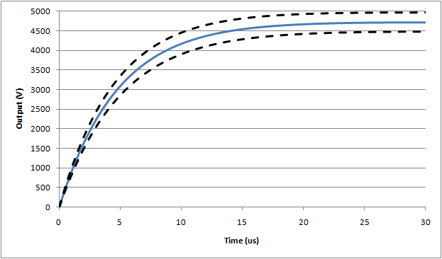
These values are historically based on older style "monophasic" defibrillators that were designed to deliver a maximum of 360J to the patient with peak voltages around 5kV and peak current of 50A. Assuming the inductor has a resistance of 5Ω, and the remaining components are nominal values, the simulated nominal waveform is as follows (this simulation is based on differential step analysis, a excel sheet using the simulation allowing component variation can be downloaded here):

The drop in peak voltage from the expected 5000V is due to the series resistance in the inductor creating a divider with the main 100Ω resistor. In this case, since 5Ω was assumed there is ~5% drop. The rise time of this waveform is mainly influenced by the inductor/resistor time constant (= L/R = 500µH / 105Ω = ~ 5µs), while the decay time is largely influenced by the capacitance/resistance time constant (32µF/105Ω = ~ 3.2ms). Again using ideal values (and 5Ω for inductor resistance), the expected values are:
Peak voltage, Vp = 4724V
Rise time (time from 30% -> 90% of peak), tr = 9.0µs
Fall time (start of waveform to to 50% of peak), tf = 2.36ms
The leading edge of the ideal waveform is shown in more detail here:
.png)
Modern defibrillators use "biphasic" waveforms with much lower peak voltages, and lower energy may be considered safer and more effective (see this article for an example). Also, as the standard points out, in the real world the voltage that appears in applied parts will be less than that delivered by the defibrillator. However, the standard continues to use the full high voltage monophasic pulse (tested at both polarities) for the basis of the test. In practice this often has little effect since the Type F insulation in equipment is usually designed to withstand 1.5kVrms for 1 minute, which is much more tough than 5kV pulse lasting for a few milliseconds. However, occasional problems have been noted due to spark gaps positioned across patient insulation areas with operating voltages around 3kV. When tested in mains operation, there is no detectable problem, but when tested in battery operation breakdown of the spark gap can lead to excess energy passing to the operator (see more details below).
For the energy reduction test (IEC 60601-1, 8.5.5.2) the standard specifies a modified set up using a 25mH inductor, rather than the 500µH specified above. Also, the inductor resistance is fixed at 11Ω. This leads to a much slower rise time in the waveform, and also a significant reduction in the peak voltage:
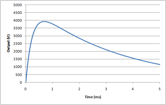
For this test, the nominal waveform parameters are:
Peak voltage, Vp = 3934V
Rise time (time from 30% -> 90% of peak), tr = 176µs
Fall time (start of waveform to to 50% of peak), tf = 3.23ms
As discussed in the calibration section below, it can be difficult to realise these waveforms in practice due to difference between component parameters measured at low current, voltage and frequency (e.g. an LCR meter), compared to actual results at high current, voltage, and frequency.
Design considerations
The following considerations should be taken by designers of equipment for defibrillator protection, and also verification test engineers (in-house or third party laboratories), prior to performing the tests to ensure that test results are as expected.
A) Common mode insulation
Solid insulation (wiring, transformers, opto-couplers)
During the common mode test, the Type F patient isolation barrier will most likely be stressed with the defib pulse. However, although the peak defib voltage is higher than F-type applied part requirements, for solid insulation an applied voltage of 1.5kVrms applied for 1 minute (2.1kVpeak) is far more stressful than 5kV pulse where the voltage exceed 2kV for less than 3ms. Thus, no special design consideration is needed.
Spacing (creepage, clearance)
According to IEC 60601-1, it is necessary to widen the applicable air clearance from 2.5mm to 4.0mm for applied parts with a defibrillator proof rating, which matches the limit for creepage distance. Since in most cases the minimum measured creepage and clearance are at the same point (e.g. between traces on a PCB), this often has little effect. However, in rare cases, such as in an assembled device, clearances may be less than creepage distances.
EMC bridging components (capacitors, resistors, sparkgaps)
For EMC, it is common to have capacitors, resistors and sparkgaps bridging the patient isolation barrier. In general, there are no special concerns since the insulation properties (1.5kVrms, 1min) ensure compliance with 5kVp defib pulse, and impedance of these components is also far higher than needed to ensure compliance with leakage current limits. Based on simulations, a 10nF capacitor or a 150kΩ resistor would result in a borderline pass/fail result for the test for operator shock (1V at the Y1-Y2 terminals), but such components would result in a leakage current in the order of 1mA during the mains on applied part test, a clear failure.
The one exception is the spark gap: provided the rating is above 5kV, there is no concern, however, cases have been noted of spark gaps rated at around 3kV, and breaking down during the test. This is of particular concern for patient monitors utilising battery operation, since in this battery operation the energy can be transferred to the operator via the enclosure (in mains operation, the energy flows to earth and causes no harm).
Although there are arguments that the 5kV peak is too high, unfortunately this is still specified in the standard, and it is recommended that any spark gaps bridging the patient isolation barrier have a rated voltage which ensures no breakdown at 5kV. In order to allow for tolerance, this may mean using a spark gap rated at around 6kV.
B) Differential insulation (general)
For equipment with multiple applied parts (such as a patient monitor), differential insulation is needed to ensure compliance with the differential test (exception is the ECG function, which is discussed below) and the energy reduction test. While this insulation can be provided in the equipment, typical implementation relies on insulation in the sensor itself, to avoid the need to design multiple isolated circuits. Typically, common temperature sensors, IBP transducers and re-useable SpO2 probes provide adequate insulation, given the relatively light electrical stress of a defib pulse (again, although it is high peak voltage, the short duration means most modern material have little problem withstanding a pulse).
However, it can be difficult for a manufacturer of a patient monitor to provide evidence of conformity for all the sensors that might be used with a monitor, since a large range of sensors can be used (in the order of 20-100), as optional accessories, and these are manufacturered by other companies. In some cases, the manufacturer of the patient monitor does not actually specify which sensors can be used, simply designing the equipment to interface with a wide range of sensors (e.g. temp, IBP, ECG electrodes).
Currently, IEC standards for patient monitors treat the device and accessories as one complete item of "equipment" . This does not reflect the actual market nor the current regulatory environment, which allows the separation of a main unit and sensors, in a way which allows interchangeability without compromising safety. Although a manufacturer of a patient monitor may go to the extreme of testing the monitor with all combinations of sensors, this test is relatively meaningless in the regulatory environment since the patient monitor has no control over design and production of the sensors (thus, for example, a sensor manufacturer may change the design of a sensor without informing the patient monitor, invalidating the test results).
In the modern regulatory environment, a system such as this should have suitable interface specifications which ensures that the complete system is safe and effective regardless of the combination of devices. To address the defibrillation issue, for example, sensor manufacturers should include a specification to withstand a 5kV defib pulse without breakdown between the applied part of the sensor (e.g. probe in in saline) and the internal electrical circuit. It is expected that manufacturers of sensors are aware of this issue and are apply suitable design and production tests. IEC standards should be re-designed to support this approach.
To date there are no reported problems, and experience with testing a range of sensors has found no evidence of breakdown. Due to failure of the standards to address this issue appropriately, test laboratories are recommended to test patient monitor equipment with the samples selected by the patient manufacturer, rather than the complete list of accessories.
There is a question about disposable SpO2 sensors, since the insulation in the sensor is not as "solid" as non-disposable types. However, provided all other applied parts have insulation, this is not a concern.
C) Differential protection (ECG)
The ECG function differs in that direct electrical connection to the patient is part of normal use. Thus, it is not possible to rely on insulation for the differential test, and there are several additional complications.
Manufacturers normally comply with the basic differential requirement by using a shunt arrangement: a component such as gas tube spark gap or MOV is placed in parallel with the leads, and shunts the energy away from the internal circuits. Since the clamping voltage of these devices is still relatively high (50-100V), series resistors after the clamping device are still needed to prevent damage to the electrical circuit. These resistors combine with input clamping diodes (positioned at the input of the op-amp) so that the remaining current is shunted through the power supply rails.
Early designs placed the clamping devices directly across the leads, which led to the problem of excessive energy being lost into the ECG, a hazard since it reduces the effectiveness of the defib pulse itself. This in turn led to the "energy reduction test", first found in IEC 60601-2-49 (only applicable to patient monitors), then part of IEC 60601-2-27:2005 and now finally in the general standard (applicable to all devices with a defib rating). To comply with this requirement, the ECG input needs additional current limiting resistors before the clamping device, so a typical design will now have resistors before and after the clamping device. From experience, resistor values of 1kΩ will provide a borderline pass/fail result, higher values of at least 10kΩ are recommended (50kΩ seems to be a typical value). While patient monitors under IEC 60601-2-49 have dealt with this requirement for many years, diagnostic ECGs will also have to comply with this requirement after the 3rd edition becomes effective. This may result in conflicts since many diagnostics ECGs try to reduce the series impedance to improve signal to noise ratios (e.g. CMRR), and may not have any resistors positioned ahead of the clamping device.
The protection network (resistors, shunt device) can be placed in the ECG lead or internal to the equipment. The circuit up to the protection network should be designed with sufficient spacing/insulation to withstand the defibrillator pulse. The resistors prior to the shunt device should be of sufficient power rating to withstand multiple pulses, taking into account normal charging time (e.g. 30s break) in between pulses.
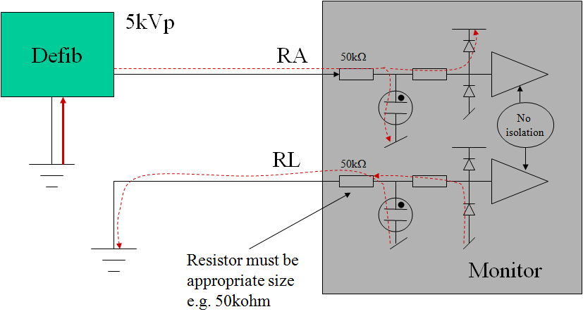
Figure: typical ECG input circuit design for defibrillator protection
An additional problem with ECG inputs is due to the low frequency, high pass filter with a pole situated around 0.67Hz for "monitoring" filter setting, and 0.05Hz for the "diagnostic" setting. A defibrillator pulse will saturate this filter (base line saturation), preventing normal monitoring for extended periods., This is a serious hazard if the ECG function is being used to determine if the defib pulse was successful. Manufacturers typically include a base-line reset function in either hardware and/or software to counter this problem. There have been cases where in a "diagnostic" setting, the baseline reset is not effective (due to the large overload), and some manufacturers have argued that the "diagnostic" mode is a special setting and therefore the requirements do not apply. However, this argument is weak if analyzed carefully using risk management principles. Even if the probability of defibrillating the patient when the equipment is in the "diagnostic setting" is low (e.g. 0.01), the high severity (death) would make it unacceptable not to provide a technical solution.
Finally, there is a testing in the ECG particulars (IEC 60601-2-25, IEC 60601-2-27) which involves use of real gel type ECG electrodes. This test is intended to determine the effects of current through the electrodes. Excessive current can damage the electrodes, causing an unstable dc offset that prevents monitoring and hence determination of a sucessful defibrillation - a critical issue. While it has all good intentions, this test unfortunately is not well designed, since it is not highly repeatable and greatly dependent on the electrodes tested. In the real world, ECG equipment is used with a wide variety of electrodes which are selected by the user, and not controlled by the manufacturer. There is little logical justification for testing the ECG with only one type of electrode. Fortunately, the energy reduction test has largely made this a irrelevant issue - in order to comply with that test, equipment now typically includes series resistors of at least 10kΩ. This series resistance also reduces the current through the gel electrodes. Experience from tests indicates that equipment with series resistors of 10kΩ or higher, there is no detectable difference between the test with electrodes and without electrodes, regardless of the type of electrode. Logically, standards should look at replacing this test with a measurement of the current, with a view to limit this to a value that is known to be compatible with standards for get electrodes (e.g. ANSI/AAMI EC12:2000 Disposable ECG electrodes, 3ed.).
Practical testing
Simplification
Testing of a single function device is relatively simple. However, testing of a multiparameter patient monitor can explode the potential number of tests. In order to reduce the number of individual tests, it is possible to use some justification based on typical isolation structures and design:
-
common mode test: this test can be performed with all applied part functions shorted together, similarly with all accessible parts (including isolated signal circuits) shorted together. If applied parts such as temp/SpO2/IBP all connect into a single circuit, make your applied part connection directly to this circuit rather than wasting time with probes in saline solution. Ensure that the test without mains connection is performed if battery powered, this will be the worst case. If with this simplification, the Y1-Y2 result is <1V, then logically tests to individual functions will also comply. Once this is confirmed, no further testing for operator protection (Y1-Y2) is needed. Because of leakage current requirements, measurements more than 0.1V (Y1-Y2) are not possible, unless a spark gap is used (see design discussion above). If a spark gap of less than 5kV is used, expect a result around 20-30V (i.e. well above the 1V limit). Prior to the test, inspect the circuit for the presense of spark gaps and confirm the rating is appropriate. See below for more details on the operator energy test (measurement).
-
differential mode test: this will need to be done with each function one by one. In theory, for non-ECG functions, the probe insulation should be verified, but in practice this is the responsibility of the probe manufacturer (see discussion above), thus usually only one representative test is performed. It is also possible in theory that capacitive current accross the insulation barrier may interupt patient monitor operation including the measurement circuits. However, experience indicates that Temp, IBP and SpO2 inputs are hardly affected by the pulse, due to high levels of software averaging and noise reduction with these types of measurement. Tests with a representative probe (ideally, the largest probe with the greatest capacitance) is considered reasonable to verify the monitor is not affected. To save time, tests with non-ECG functions should be performed first with the 0.5mH/50Ω set up to confirm no damage, no detectable impact to function (i.e. measurement accuracy); and then change to the 25mH/400Ω set up for the energy reduction test. Refer to particular standards special test conditions (for example, IEC 60601-2-34 requires the sensor to be pressurised at 50% of full scale, typically 150mmHg)
ECG testing is more complicated in that there are many different leads, filter settings and failed results are not uncommon. Refer to the set up in the standards (IEC 60601-2-25, IEC 60601-2-27). Additional notes are: It is recommended to limit tests with the monitoring setting to RA, LA, LL, V1, V6 and N (RL) , with V2 - V5 skipped since the design of V1 - V6 is common. Usually for testing to N (RL), no waveform is possible, so recovery time cannot be measured, but it should still be confirmed that the monitor is functional after the test. For "diagnostic" and other filter settings, testing of RA, LA, LL only is justified (V1 ~ V6 are not intended to be used for seeing if the defibrillation is effective). Keep records (strip printouts) of representative tests only rather than all tests, unless a failed result occurs. Keep in mind that some monitors allow the waveform to drift over the screen, this should not be considered a non-conformity as long as the waveform is visible. Take care with excessively repeating tests in a short period to a single lead, as this can damage the internal resistors. Careful inspection of the standards (general, ECG related) indicates that for differential mode, only a three tests should be performed (2 x 0.5mH, +/-; 1 x 25mH + only).
-
energy reducton test: for this test you will need an oscilloscope with a high voltage probe and an integration function (modern oscilloscopes provide for this function, or data download to excel for analysis). Energy can be determined from the integration of V2/R (E = ∫ v(t)2dt) / R), measured directly accross the 100Ω resistor. Experiment without the device connected to get a value around 360J (a reduction from 400J is expected due to the resistance of the inductor). The following set up problems have been noted:
- with some older types of oscilloscopes, n calculation overflow can occur due to squaring high voltage, this can be countered by moving the equation around (i.e. moving the 1/R inside the integration, or ignoring the probe ratio and setting the range to 1V/div rather than 1000V/div).
- the capacitor's value will vary as the capacitor and equipment heats up, and this may result in around 2-3% change between pulses. This may be countered by charging/discharging several times before starting tests. Even after this, variations of 1-2% between pulses can be expected.
As discussed above, non-ECG sensors rarely breakdown, and for the ECG function, provided the manufacturer has included appropriately rated series resistors of 10kΩ or higher, the result will clearly in compliance despite set up variabilities. If the manufacturer uses only 1kΩ series resistors in the ECG function, a borderline (failed) result can be expected. Inspect the circuit in the cable and equipment before the test.
- operator energy test (measurement): This test measures the voltage between Y1-Y2. A value of 1V represents 100µC charge passing through the equipment to the operator. As discussed above, there is no expected design which will result in a borderline pass/fail, either there will be only noise recorded (<0.1V), or a complete failure (>20V). From experience, as there is a tendency for the pick up of noise in the oscilloscope seen as a spike of >1V and less than 5ms. The output of the set up is such that a "true result" should be a slowly decaying waveform (τ = 1µF x 1MΩ = 1s), so that any short duration spike can be ignored. Alternately, the Y1-Y2 output can be connected to a battery operated multimeter with 10MΩ input and peak hold (min/max) function. With a 10MΩ input, the decaying waveform has a time constant of 10s, easily allowing the peak hold to operate accurately. The battery operation ensures little noise pick up, and continuous monitoring helps to ensure the 1µF capacitor is fully discharged before the test.
Test equipment calibration
Calibration of defib testing equipment is extremely complicated, since the standard only specifies component values, with relatively tight tolerances. It is arguable that this is an erroneous approach, partly because of the difficulties in measurement of internal components, but mainly due to the reality that measurement of component values at low voltage, current and frequency (e.g. DMM and or LCR meters) is not reflective of the values of these components under high voltage, high current and high frequency conditions of use. For example, an inductor measured at 1kHz with a low current low voltage LCR is unlikely to be representative of the inductor's real value at peak currents of 50A, rise times of <10µs (noting for example, skin/parasitic effects at high current/frequency), and with a coil stress likely to be exceeding 100V/turn. Therefore, it is justified (as many laboratories do) to limit the calibration to a few values and inspection of the output waveform. The following items are recommended:
- the accuracy of meter displaying the dc charging voltage (limit is not clearly specified, but recommended to be ±1%)
- monitoring of the waveform shape to be within an expected range (see 3 waveforms below, also download excel simulator from here)
- measurement of the 100Ω, 50Ω and 400Ω resistors
- measurement of the Y1-Y2 voltage with a known resistor (see below)
Based on simulations, the following waveforms show the nominal (blue line), and outer range assuming worst case tolerances as allowed by the standard (±5%):
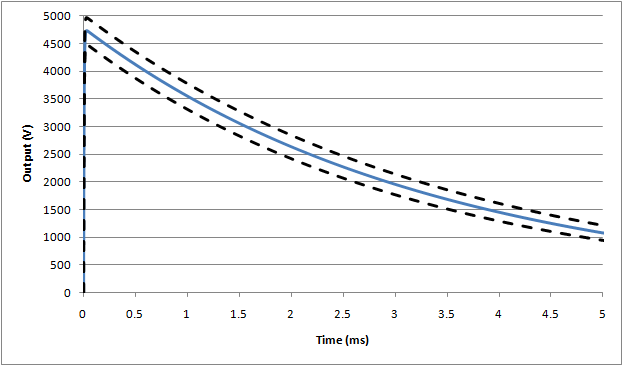
Waveform #1: 500µH (full waveform), nominal assumes 5Ω inductor resistance
Waveform #1: 500µH (expanded rise time), nominal assumes 5Ω inductor resistance
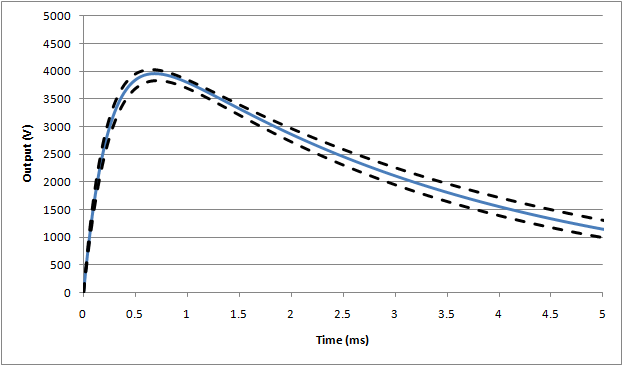
Waveform #3: 25mH (full waveform)
If, as can be expected, actual waveforms do not comply within these limits, the following extenuating circumstances may be considered: if the rise time and peak values are higher than expected (likely due to problems with the series inductor), this waveform can be considered as being more stressful than the requirements in the standard. Since the design of equipment is not expected to fail, equipment that passes under higher rise time/voltage conditions can be considered as complying with the standard.
For the operator energy circuit, the circuit can be tested by replacing the device under test with a resistor. Using simulations (including the effect of the diodes), the following resistor values yield:
100.0kΩ ⇒ Y1-Y2 = 1.38V
135.6kΩ ⇒ Y1-Y2 = 1.00V
141.0kΩ ⇒ Y1-Y2 = 0.96V
150.0kΩ ⇒ Y1-Y2 = 0.90V
The 141kΩ can be made up of 3 series 47kΩ, 0.25W standard metal film resistors. The expected energy per pulse is only 85mW/resistor. If other types of resistors are used, ensure they are suitably non-inductive @ 100kHz.
Since there are several components in this circuit, and taking into account the nature of the test, outputs within 15% of the expected value can be considered to be calibrated.
[End of material]