Many medical devices include alarms, and both collateral and particular standards specify sound level measurements.
But, there is a trap: the beeping sounds from alarms often have strong tones. When a sound is made up of tones, reflections create an interference pattern where the difference between spatial maximum and minimums in the region of interest can be in the order of 10dB.
 You can experience this by simply playing a 1kHz tone from your PC (click on the MP3 file right). As you play this file, walk around the room very slowly and note the changes in sound level. The interference pattern is caused by reflected sound from walls and the floor which can either add or subtract with the direct sound depending on the phase difference at the point in space. If you are careful, you can find places where the sound almost disappears as the reflected waves cancel out the direct wave. For a 1kHz waveform, these peaks and troughs should around 15-20cm apart. As the frequency increases, the space between the peaks and troughs will reduce.

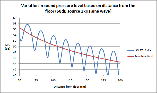
You might expect that this problem is eliminated by using the “free field over a reflecting plane as specified in ISO 3744”, referenced in IEC 60601-1-8 and a number of particular standards. But it turns out that the strongest reflection will actually come from the “reflecting plane” - a scientific term meaning the floor - and this reflection alone can cause a large interference pattern. The above graphs are actually simulated using only a single reflecting plane (floor). The graph on the left is the expected variation as a meter is kept at 1m above the floor and moved away from the sound source. The graph on the right is the variation with the sound level meter 1m away, and the height from the floor for both the source and meter is varied. The location of the peaks and valleys will also change with the frequency of the source.
It's also reasonable to expect that the requirement in IEC 60601-1-8 to have at least 4 harmonics within the 1kHz to 4kHz will fix this issue, since the reflection pattern will be different at different frequencies. But the standard allows up to ±15dB between harmonics and the fundamental, which is rather large. The upshot is that one particular harmonic can easily dominate the sound level measurement.
Moreover the test sample, and any supporting device such as a table is not a point source. Simulations show that a rectangular object emitting sound in free space will still create an interference pattern, simply due to the different time that sound from different parts of rectangle reach a certain point in space.
To put it bluntly, trying to measure sound pressure is a mugs game for sounds with strong, discrete tones.
So what is going on? How can we have a fixed requirements when the test method is hopelessly unrepeatable?
It turns out there is a fundamental error in medical standards that reference ISO 3744. The standard ISO 3744 is intended to estimate the sound power level from the source. It does this by taking many sound pressure measurements (up to 20) around a surface which encloses the noise source against the reflecting plane. These measurements are then integrated to find the power level from the source itself. The spacing of these measurements is such that interference patterns are largely canceled out, so the test environment does not have to be a perfect anechoic chamber, rather the test is intended for use in a broad range of locations. The standard also correctly assumes that sound will not emanate from a single point (i.e. the speaker), but rather that all parts of the enclosure will be involved in the transmission of sound to the outside world; again multiple measurements help to "collect" all the sound power irrespective of the shape of the test item. The reflecting plane(s), while causing an interference pattern, also help to reflect the sound power to the measurement points.
What's the difference between sound power and sound pressure? It's a bit like power and temperature. Think of a 10 ohm resistor in a power supply which has 2Arms flowing through it. We can estimate the power of the resistor quite accurately as 40W. The power emitted is relatively independent of the environment. But the temperature of a part 10cm away from the power resistor is a complex function of many factors, the physical layout, material properties, air flow and so on. We know that increasing the power increases the temperature, but we cannot predict the actual temperature without measuring it. And most importantly, even though we measure the temperature of one part 10cm away, it does not mean that all parts at 10cm have the same temperature.
In the same way, a speaker will emit a fairly constant amount of sound power irrespective of the environment. However, the sound pressure will be complex function depending on the environment, including construction of the medical device itself (in much the same way as the speaker's box also influences sound pressure). A measurement a one point 1m away will not be representative of another point 1m away. However, by taking many sound pressure measurements around an object, we can use the properties of air and the surface area of the measurement framework to estimate the sound power from the source.
One reason why we quickly become confused between sound power and pressure is they both use a dB scale. However, the underlying units are the watt (W) and Pascal (Pa). The dB scale simply reflects a wide range over orders of magnitude. Sound power and sound pressure are as different as resistor power and resistor temperature - they are related but definitely not the same thing.
It appears the IEC 60601 series has originally fallen for the trap of treating sound power and sound pressure as the same thing, and in doing so ignored many of the issues associated with measurement of sound pressure.
Fortunately, the committee for IEC 60601-1-8 has finally woken up to this, and in the latest amendment 1 issued in 2012 now a number of measurements are required according to Annex F in ISO 3744, with the measurements averaged. Although they missed the final step of converting sound pressure to sound power, the process of averaging in effect acheives a similar purpose. A word of warning though to the unsuspecting; averaging sound pressure is not simply averaging the readings in dB. To get the correct average, the readings should be in pressure, which means first converting to a non-logrithmic representation, averaging, and then convert back to dB. Mathematically it is not necessary to convert to any particular unit of pressure, the main point is that the average should be performed on the "anti-log" representation. For example, three values 72, 70 and 62dB incorrectly averaged in dB gives 68dB, but if averaged in pressure and converted back is 69.75dB, roughly 2dB higher.
While the 2012 amendment is an improvement, technical issues remain:
-
Annex F is intended for measurements at least 4m away from the source. The calculations of the measurement points in Table F.1 refer to Table F.2, which only has values for 4m and above. Since IEC 60601-1-8 clearly specifies a measurement radius of 1m, it appears to be a technical oversight making the standard impossible to use. Further checking in the standard reveals that Annex F is intended for outdoor noise measurements, where reflections are not expected (e.g. not for indoor). Even ignoring the technical mismatch with Table F.2, it seems possible the measurements under Annex F will not yield repeatable results.
-
For the measurement of harmonics, the standard specifies a single point measurement 1m away from the equipment. However, both theoretical analysis and experimental evidence show that harmonics vary greatly with the small changes in the position of the sound level meter. This is because the interference pattern will be different for each frequency (again, even the reflecting floor will produce interference patterns). The requirements for harmonics are relative, so ignoring reflections the exact position of the meter is not critical. To eliminate the effect of reflections, it is recommended the measurements should be made with the meter positioned fairly close to the equipment's speaker, e.g. 5cm away. Experiments with this found the relative harmonics to be consistent when measured close to the equipment, irrespective of the exact position of the meter.
-
For relative priority (high > medium > low), the measurements rely on Annex F at 1m, which is still influenced by reflections and high uncertainty. Designers often only have a small difference between the sound level of different types of alarms, so errors in the test method can produce false negative results. Since the measurements are relative, it again makes sense to use a single point measurement at a point close to the equipment where the influence of reflections and the interference pattern are negligible.
In general, a formal test for sound level measurement according to ISO 3744 can be expensive yet still give poor quality results. Also, a major point in the whole test is missing; an appropriate criteria. Criteria have been specified for harmonics, pulse characteristics, and relative priority and these are fairly easy to measure with relatively at low cost (noting the technical points above). But the main criteria in the standard for the ISO 3744 sound level measurement is simply to match what is disclosed in the instructions for use. This does not address the original point of the risk control: getting the operator's attention. According to the fundamentals of risk management, we need to judge if a risk control is effective, which in turn will require a judgment on whether the sound level is sufficient. This is certainly difficult and complex subject, but nevertheless, unless a criteria is developed, there seems little point in making expensive and complicated sound level measurements.
So what is the solution?
One possibility is to formally change the criteria to sound power, rather than sound pressure, with a simple reference to measurements under ISO 3744. There is no need to specify the position or radius of measurement and so, use of Annex F etc, these are all handled in ISO 3744 and are judgments made by test lab.
Experiments could then be performed to develop appropriate ranges for sound power for typical situations, e.g. operator always near the equipment (within 1m); an operator in a quiet medium sized room (e.g. operating theater); noisy medium size room (e.g. general ward) and so on.
Finally, a manufacturer could choose to bypass the ISO 3744 test by estimating sound power from the speaker specifications. Although there is greater uncertainty with this method, it might be more reasonable if the sound level is adjustable. And given that sound power measurements are anyhow fairly rough, this method may yield similar uncertainty to actual measurements. This method also frees the manufacturer to make design or option changes without having to retest the equipment.
For example, a patient monitor may come with various optional modules, and the attachment of the modules will affect the acoustic properties. Under the current standard, a strict interpretation would require all versions to be tested at great expense, and as well any design changes that could affect the acoustic pressure. But if the limits are changed to power, as long as the speaker is not changed we can expect the acoustic power to be similar irrespective of the model or design variations.
All of this needs some research and experiments before being put into a standard; but one thing is clear, something has to be done to improve the current situation and avoid unreasonable use of limited resources.