
Li-ion batteries - the anecdotal PCM story

If you are new to Li-ion batteries and standards compliance in the context of IEC 60601-1, the area can be confusing - largely because there is some messy history. Normally with a high risk part such as this you can buy it off the shelf, all nicely certified, well specified, just plug and play.

To a large extent battery manufacturers have done their job well, especially if you are dealing a reasonably well known, quality battery maker. The weak point is mostly on the standards and third party testing. It is improving, and perhaps in a few years an article like this will no longer be needed.

OK, before we start some basic terms.

Standards refer to “primary” and “secondary” cells or batteries - translated this means “non-rechargeable” and “re-chargeable” respectively.

Standards also refer to “cell” and “battery”. Normally lay people mix up battery and cells, while us experts know that “battery” means two or more cells. Well, forget that. For IEC standards, a “battery” means one or more cells together with any necessary protective features. Any sizable cell will normally have a PCM or Protection Circuit Module, so even a single cell with a PCM is referred to as a “battery”.

This article is intended for a re-chargeable cells with a size large enough to need a PCM, i.e. secondary batteries. Anecdotally, the threshold for this seems to be around 50mAh, although no literature has been found to support this. This article, by the way, is all anecdotal - please use it to power your own research, but not as a resource itself.

Now for some basics on Li-ion safety.

Li-ion is generally safe compared to the original lithium metal batteries. However, under overload, short, overcharging and age, the Li-ion can convert to metal and become highly flammable. In order to protect against this, most cells will have three protection features inside the cell, including a PTC for overcurrent, a pressure switch for overcharging (triggered by gas production), and finally a vent (weak point) to release pressure in case the other two fail.

But … these protection features are not what we would call super reliable. They might work, say, 19 out of 20 times. I have no idea of the actual value, only that it’s nowhere near the normal reliability we would expect for a safety feature associated with fire.

Thus, once the cell gets to a certain size, say >50mAh, most manufacturers will fit a PCM. This is a small electronic circuit that watches the cell voltage, charge and discharge currents and disconnects the battery if anything exceeds the limits. It’s usually built into the pack, a small PCB at the top which can sometimes be seen if the final wrap is clear. There are many dedicated ICs that can perform this function with just a few external components, and there are ICs for multi-cell packs that can watch each cell individually. The PCB also often contains a 10k NTC thermistor - more on that later.

This “battery”, which contains cell(s) with protective features (PTC , PS, PV) plus the PCM is what you will typically find on the market today. As long as the end product manufacturer makes sure the charging circuit fits within the normal condition limits as specified by the battery manufacturer (currents, voltages, profiles, temps) then the overall system is safe in normal and single fault condition. Plug and play.

So far so good. But in the modern world, for high risk things like preventing fire it is not enough to trust a spec sheet: it has to be verified in design and production, with regulatory records. To avoid that every end user has to audit the battery manufacturer, we normally rely on third party certification.

This is where things fall off the rails.

Third parties are generally good at all the cell side of things - cells normally have a bunch of stress tests thrown at them to show they are unlikely to explode or catch on fire. However, for larger cells the charging voltage is normally limited during testing to the values specified by the manufacturer, for example 4.35V for a typical 3.7V cell.

Why?

My guess - historically, UL were the market leader, UL1642 certified cells were (are?) the defacto standard. Knowing that larger cells can occasionally explode if overcharged, their approach was to test to the limits specified by the manufacturer (e.g. 4.35V) and then “list” the cells using these limits, requiring that the end user would ensure these limits are not exceeded in normal and single fault condition.

End product manufacturers however, not being aware of the dangers, often missed the “single fault condition” part and designed chargers around normal condition only, typically 4.25V. In fact, the only way to cover the single fault condition successfully is to have a fully independent circuit between the charger and the battery, something that is not intuitive for an end product designer. Moreover, in the case of a series of cells (e.g. 7.2V, 14.8V packs) it is not possible to monitor the individual cell voltage external to the pack, so UL’s approach was actually an impossible to meet.

Battery manufacturers knew this, and started fitting PCMs to packs to handle the single fault condition. It’s perhaps a rare case where manufacturers got ahead of the agencies, which in turn clearly indicates that Li-ion is definitely dangerous stuff. If it was all just theoretical, there is no way the PCMs would be fitted unless pushed by the agencies.

It’s also possible that agencies knew about the importance of PCMs but were reluctant to accept electronic based protection: historically “protection” is in the form of fuses, circuit breakers, optocouplers, insulation, earthing, where the protection itself can be tested for various aspects reliability. Electronic circuits don’t lend themselves to this kind of verification. In the real world though, the PCM is a very simple circuit and modern electronics is generally reliable - like 10-9 events per year kind of realm - in practice a PCM is far more reliable than a fuse or circuit breaker.

That of course is history, and standards and third parties are catching up. The latest standard IEC 62133-2:2017, which is dedicated for re-chargeable Li-ion cells and batteries, does allow for testing that includes the PCM.

However this standard was only released in 2017, so much of the documentation on Li-ion batteries may pre-date this. The older standard IEC 62133 does not reliably test the PCM, nor does UL1642 or UL2054 listings.

Confusingly, IEC 62133-2 can be used for both cells and batteries. If the report is just for the cells it won’t cover the PCM and various other tests. By using the same standard number for cells and batteries means that users need to look into the report to figure out what is going on. I guess that in the future we may see a new standard covering a “battery pack”, to mean an object that has all the protective features built in, that the end user can really just plug and play.

A side issue is that battery packs are often custom designed, and there are a wide range of sizes and shapes available, some are fairly specialized and low volume. Forcing manufacturers into third party certified pack route may not be feasible. Thus a real long term solution may also see a consolidation and standardization of the available pack size, ratings, and physical shape, which itself may not be a bad thing.

OK, with all that in mind, how to deal with Li-ion batteries and IEC 60601-1?

For secondary batteries, IEC 60601-1/A1:2012 Clause 15.4.3.4 refers to an compliance with IEC 62133. Since this is undated, technically the latest edition should be used, which is IEC 62133-2:2017. It’s also important to note that the standard refers to “secondary batteries” not “secondary cells”, which in turn means that the PCM, if required for safety, must be included in the testing.

Note that if you are reading the earlier version of IEC 60601-1:2005, it has an incorrect reference to IEC 60086-4 which is only for primary or non-rechargeable batteries. This was corrected in A1:2012.

When you ask battery manufacturers for evidence of compliance they may provide a few different things:

Some may provide reports for the old IEC 62133:2012. This standard may be OK for the cell, but it may not cover the PCM.

Some manufacturers may point to UL1642 listing. This is an older standard, and not IEC aligned, but is reasonably seen as equivalent to IEC 62133. However, it again it is just for the cell and does not cover the PCM.

If you are lucky, the manufacturer might provide a report for IEC 62133-2:2017 which is the the newer version and covers the PCM. However, you need to check the report (not just for example, the CB certificate) to make sure it is for the battery pack and not just the cells. Also reports (and CB Certificates), only cover the samples tested, and don’t cover regular production. Legally, you need to be covered for design and production. As such, even if you have a report, it’s recommended to ask for a declaration of conformity, since a properly prepared declaration covers both design and regular production. Make sure the declaration refers to IEC 62133-2:2017 (dated), and make sure it covers the pack with the PCM, not just the cells.

If you are really lucky you might get:

  • UL listing to UL62133-2:2020. This UL standard is fully harmonized with IEC 62133-2:2017 and covers the PCM, and if the part is UL listed this means it includes a factory inspection (i.e. production is covered)

  • any other private certification marks such as TUV SUD, TUV Rh, VDE etc, which has the latest standard (IEC 62133-2:2017) and includes factory inspection.

These last two are truly plug and play. However, it is expect these will take a while to get popular.

In the mean time, what to do if really like the pack but the evidence is weak and may not cover the PCM?

The first point is to check if a PCM is fitted. This is usually indicated in the specification sheet.

Next, there are a few options, which could be taken in combination:

  1. Trust the manufacturer: if it is a well known brand this might be enough for some users

  2. Ask the manufacturer for a declaration of conformity to IEC 62133-2:2017 covering the battery pack with the PCM installed (as above)

  3. Periodically inspect and test packs for implementation and correct operation of the PCM. Note this needs to be done in a safe way considering the risks of exploding batteries.

If there is no PCM or the implementation cannot be confirmed, it’s also possible to fit your own PCM external to the pack, provided that it is single cell only.

If the cell is small enough that a PCM is not required, note that this still needs evidence. The cell certification should be compatible with the voltage/current available in fault condition from the end product. For example, if the charging IC is run off a 5V/500mA USB supply, then if the charging IC fails, these would be the most expected in fault condition. If you have say UL1642 cells certified to 5V/1A, then that might be enough.

Apart from above, from experience end product manufacturers sometimes mess up the charging characteristics. Most charging ICs are flexible and there are several parameters which can be set by external components. It’s always worth having an independent engineer double check the calculations. Wireless chargers have extra complexity and worth to double check the charging parameters and profile is as expected.

In 2007 the Japanese organisation JEITA issued a guideline on temperature limitations for Li-ion charging. Many chargers now work with these limits, using an NTC that is situated close to or inside the pack. It is recommended to use this feature if possible to maintain battery life and for additional safety (less chance of the other protective features being activated). Many packs have a third lead with a 10k NTC fitted for this purpose.

These last two points are technically covered by IEC 60601-1 Clause 4.8, which requires that components are used within specification. However, not all test agencies will check the detail, so it’s worth double checking internally with an independent engineer.

In addition to IEC 60601-1, most people would have heard of UN 38.3 which covers shipping. I’m not an expert on this, but I assume a declaration might be needed before agencies like DHL, FedEx, UPS etc will accept batteries for shipping.

There is also an EU battery directive. Again it is not an area of expertise but from memory there is a requirement to provide a practical method for removing the batteries for disposal. In other words, simply saying “dispose of according to national regulations” in the IFU may not be enough.

A final reminder! All information here is provided to help designers get started, but should not be used as a formal reference. Always check the source regulations, standard etc for the final decision, and if necessary engage qualified experts.

IEC 60601-1 Defibrillator protection (design, test)

This article is copied from the original MEDTEQ website, originally published around 2009
~~~~~~~~~~~~~~~~~~~~~~~~~~~~~~~~~~~~~~~~~~~~~~~~~~~~~~~~~~~~~~~~~~~~~~~~~~

Introduction

Defibrillator proof testing is common for equipment associated with patient monitoring, HF surgical (neutral electrode) and ECG, and any device that may remain attached to a patient during defibrillation. In order to speed up delivery of the defibrillator pulse, it is desirable to leave many of the applied parts connected to the patient; thus such applied parts should be able to withstand a pulse without causing an unacceptable risk. In general, a defibrillator proof specification is optional, however, particular standards may specify that it is mandatory (for example, ECG related).

This section covers the following topics related to defibrillator proof testing (defib testing):

Potential hazards / Defibrillator pulse characteristics / Design considerations / Practical testing / Test equipment calibration

Potential hazards

The potential hazards associated with the use of a defibrillator when other equipment is connected to the patient are:

  • permanent damage of medical equipment attached to the patient
  • loss of critical data, settings, operation for monitoring equipment attached to the patient
  • inability of monitoring equipment to operate to determine the status of the patient (after defibrillation)
  • shunting (loss) of defibrillator energy
  • conduction of defibrillator energy to the operator or unintended locations in the patient

All of these are addressed by IEC 60601-1:2005 (Clause 8.5.5), although particular standards such as IEC 60601-2-27 (ECG, monitoring) may specify more detail in the compliance criteria. The tests identify two paths in which the defibrillator pulse can stress the equipment: 

  • Common mode: in this case the voltage typically appears accross patient isolation barriers associated with Type F insulation.
  • Differential mode: in this case the voltage will appear between applied parts

Design and testing considerations for both of these modes are detailed below.

Defibrillator pulse characteristics

For the purpose of testing other than the shunting of energy, the standard specifies a defib pulse sourced from a 32uF capacitor, charged to 5000V (equivalent to 400J), which is then discharged via series inductor (500µH, max 10Ω). For copyright reasons, please refer to the standard for the actual circuit diagram.

These values are historically based on older style "monophasic" defibrillators that were designed to deliver a maximum of 360J to the patient with peak voltages around 5kV and peak current of 50A. Assuming the inductor has a resistance of 5Ω, and the remaining components are nominal values, the simulated nominal waveform is as follows (this simulation is based on differential step analysis, a excel sheet using the simulation allowing component variation can be downloaded here): 


The drop in peak voltage from the expected 5000V is due to the series resistance in the inductor creating a divider with the main 100Ω resistor. In this case, since 5Ω was assumed there is ~5% drop. The rise time of this waveform is mainly influenced by the inductor/resistor time constant (= L/R = 500µH / 105Ω = ~ 5µs), while the decay time is largely influenced by the capacitance/resistance time constant  (32µF/105Ω = ~ 3.2ms). Again using ideal values (and 5Ω for inductor resistance), the expected values are:

Peak voltage, Vp = 4724V
Rise time (time from 30% -> 90% of peak), tr = 9.0µs
Fall time (start of waveform to to 50% of peak), tf = 2.36ms

The leading edge of the ideal waveform is shown in more detail here:

Modern defibrillators use "biphasic" waveforms with much lower peak voltages, and lower energy may be considered safer and more effective (see this article for an example). Also, as the standard points out, in the real world the voltage that appears in applied parts will be less than that delivered by the defibrillator. However, the standard continues to use the full high voltage monophasic pulse (tested at both polarities) for the basis of the test. In practice this often has little effect since the Type F insulation in equipment is usually designed to withstand 1.5kVrms for 1 minute, which is much more tough than 5kV pulse lasting for a few milliseconds. However, occasional problems have been noted due to spark gaps positioned across patient insulation areas with operating voltages around 3kV. When tested in mains operation, there is no detectable problem, but when tested in battery operation breakdown of the spark gap can lead to excess energy passing to the operator (see more details below). 

For the energy reduction test (IEC 60601-1,  8.5.5.2) the standard specifies a modified set up using a 25mH inductor, rather than the 500µH specified above. Also, the inductor resistance is fixed at 11Ω. This leads to a much slower rise time in the waveform, and also a significant reduction in the peak voltage:
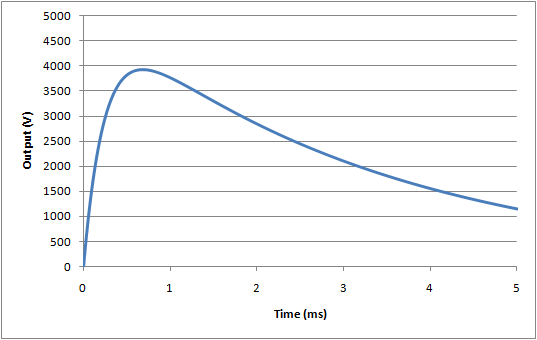
For this test, the nominal waveform parameters are:

Peak voltage, Vp = 3934V
Rise time (time from 30% -> 90% of peak), tr = 176µs
Fall time (start of waveform to to 50% of peak), tf = 3.23ms

As discussed in the calibration section below, it can be difficult to realise these waveforms in practice due to difference between component parameters measured at low current, voltage and frequency (e.g. an LCR meter), compared to actual results at high current, voltage, and frequency.

Design considerations

The following considerations should be taken by designers of equipment for defibrillator protection, and also verification test engineers (in-house or third party laboratories), prior to performing the tests to ensure that test results are as expected.

A) Common mode insulation
Solid insulation (wiring, transformers, opto-couplers)

During the common mode test, the Type F patient isolation barrier will most likely be stressed with the defib pulse. However, although the peak defib voltage is higher than F-type applied part requirements, for solid insulation an applied voltage of 1.5kVrms applied for 1 minute (2.1kVpeak) is far more stressful than 5kV pulse where the voltage exceed 2kV for less than 3ms. Thus, no special design consideration is needed.

Spacing (creepage, clearance)

According to IEC 60601-1, it is necessary to widen the applicable air clearance from 2.5mm to 4.0mm for applied parts with a defibrillator proof rating, which matches the limit for creepage distance. Since in most cases the minimum measured creepage and clearance are at the same point (e.g. between traces on a PCB), this often has little effect. However, in rare cases, such as in an assembled device, clearances may be less than creepage distances.

EMC bridging components (capacitors, resistors, sparkgaps)

For EMC, it is common to have capacitors, resistors and sparkgaps bridging the patient isolation barrier. In general, there are no special concerns since the insulation properties (1.5kVrms, 1min) ensure compliance with 5kVp defib pulse, and impedance of these components is also far higher than needed to ensure compliance with leakage current limits. Based on simulations, a 10nF capacitor or a 150kΩ resistor would result in a borderline pass/fail result for the test for operator shock (1V at the Y1-Y2 terminals), but such components would result in a leakage current in the order of 1mA during the mains on applied part test, a clear failure.

The one exception is the spark gap: provided the rating is above 5kV, there is no concern, however, cases have been noted of spark gaps rated at around 3kV, and breaking down during the test. This is of particular concern for patient monitors utilising battery operation, since in this battery operation the energy can be transferred to the operator via the enclosure (in mains operation, the energy flows to earth and causes no harm).

Although there are arguments that the 5kV peak is too high, unfortunately this is still specified in the standard, and it is recommended that any spark gaps bridging the patient isolation barrier have a rated voltage which ensures no breakdown at 5kV. In order to allow for tolerance, this may mean using a spark gap rated at around 6kV.

B) Differential insulation (general)

For equipment with multiple applied parts (such as a patient monitor), differential insulation is needed to ensure compliance with the differential test (exception is the ECG function, which is discussed below) and the energy reduction test. While this insulation can be provided in the equipment, typical implementation relies on insulation in the sensor itself, to avoid the need to design multiple isolated circuits. Typically, common temperature sensors, IBP transducers and re-useable SpO2 probes provide adequate insulation, given the relatively light electrical stress of a defib pulse (again, although it is high peak voltage, the short duration means most modern material have little problem withstanding a pulse).

However, it can be difficult for a manufacturer of a patient monitor to provide evidence of conformity for all the sensors that might be used with a monitor, since a large range of sensors can be used (in the order of 20-100), as optional accessories, and these are manufacturered by other companies. In some cases, the manufacturer of the patient monitor does not actually specify which sensors can be used, simply designing the equipment to interface with a wide range of sensors (e.g. temp, IBP, ECG electrodes).  

Currently, IEC standards for patient monitors treat the device and accessories as one complete item of "equipment" . This does not reflect the actual market nor the current regulatory environment, which allows the separation of a main unit and sensors, in a way which allows interchangeability without compromising safety. Although a manufacturer of a patient monitor may go to the extreme of testing the monitor with all combinations of sensors, this test is relatively meaningless in the regulatory environment since the patient monitor has no control over design and production of the sensors (thus, for example, a sensor manufacturer may change the design of a sensor without informing the patient monitor, invalidating the test results).

In the modern regulatory environment, a system such as this should have suitable interface specifications which ensures that the complete system is safe and effective regardless of the combination of devices. To address the defibrillation issue, for example, sensor manufacturers should include a specification to withstand a 5kV defib pulse without breakdown between the applied part of the sensor (e.g. probe in in saline) and the internal electrical circuit. It is expected that manufacturers of sensors are aware of this issue and are apply suitable design and production tests. IEC standards should be re-designed to support this approach.

To date there are no reported problems, and experience with testing a range of sensors has found no evidence of breakdown. Due to failure of the standards to address this issue appropriately, test laboratories are recommended to test patient monitor equipment with the samples selected by the patient manufacturer, rather than the complete list of accessories.

There is a question about disposable SpO2 sensors, since the insulation in the sensor is not as "solid" as non-disposable types. However, provided all other applied parts have insulation, this is not a concern.

C) Differential protection (ECG)

The ECG function differs in that direct electrical connection to the patient is part of normal use. Thus, it is not possible to rely on insulation for the differential test, and there are several additional complications.

Manufacturers normally comply with the basic differential requirement by using a shunt arrangement: a component such as gas tube spark gap or MOV is placed in parallel with the leads, and shunts the energy away from the internal circuits. Since the clamping voltage of these devices is still relatively high (50-100V), series resistors after the clamping device are still needed to prevent damage to the electrical circuit. These resistors combine with input clamping diodes (positioned at the input of the op-amp) so that the remaining current is shunted through the power supply rails.

Early designs placed the clamping devices directly across the leads, which led to the problem of excessive energy being lost into the ECG, a hazard since it reduces the effectiveness of the defib pulse itself. This in turn led to the "energy reduction test", first found in IEC 60601-2-49 (only applicable to patient monitors), then part of IEC 60601-2-27:2005 and now finally in the general standard (applicable to all devices with a defib rating). To comply with this requirement, the ECG input needs additional current limiting resistors before the clamping device, so a typical design will now have resistors before and after the clamping device. From experience, resistor values of 1kΩ will provide a borderline pass/fail result, higher values of at least 10kΩ are recommended (50kΩ seems to be a typical value). While patient monitors under IEC 60601-2-49 have dealt with this requirement for many years, diagnostic ECGs will also have to comply with this requirement after the 3rd edition becomes effective. This may result in conflicts since many diagnostics ECGs try to reduce the series impedance to improve signal to noise ratios (e.g. CMRR), and may not have any resistors positioned ahead of the clamping device.

The protection network (resistors, shunt device) can be placed in the ECG lead or internal to the equipment. The circuit up to the protection network should be designed with sufficient spacing/insulation to withstand the defibrillator pulse. The resistors prior to the shunt device should be of sufficient power rating to withstand multiple pulses, taking into account normal charging time (e.g. 30s break) in between pulses.
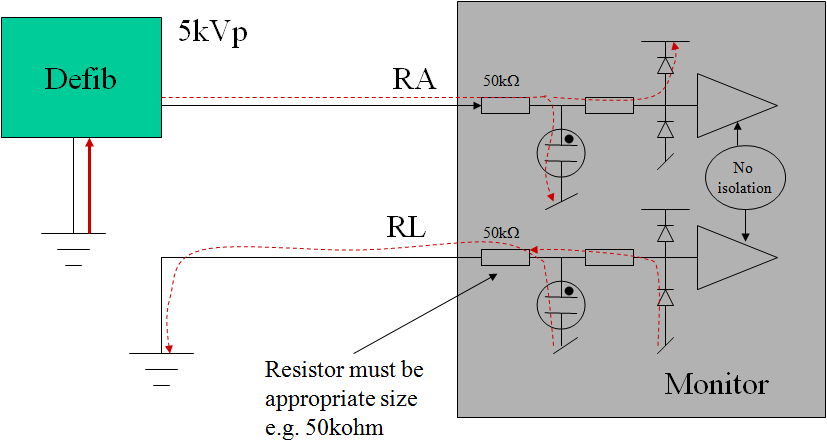
Figure: typical ECG input circuit design for defibrillator protection

An additional problem with ECG inputs is due to the low frequency, high pass filter with a pole situated around 0.67Hz for "monitoring" filter setting, and 0.05Hz for the "diagnostic" setting. A defibrillator pulse will saturate this filter (base line saturation), preventing normal monitoring for extended periods., This is a serious hazard if the ECG function is being used to determine if the defib pulse was successful. Manufacturers typically include a base-line reset function in either hardware and/or software to counter this problem. There have been cases where in a "diagnostic" setting, the baseline reset is not effective (due to the large overload), and some manufacturers have argued that the "diagnostic" mode is a special setting and therefore the requirements do not apply. However, this argument is weak if analyzed carefully using risk management principles. Even if the probability of defibrillating the patient when the equipment is in the "diagnostic setting" is low (e.g. 0.01), the high severity (death) would make it unacceptable not to provide a technical solution.

Finally, there is a testing in the ECG particulars (IEC 60601-2-25, IEC 60601-2-27) which involves use of real gel type ECG electrodes. This test is intended to determine the effects of current through the electrodes. Excessive current can damage the electrodes, causing an unstable dc offset that prevents monitoring and hence determination of a sucessful defibrillation - a critical issue. While it has all good intentions, this test unfortunately is not well designed, since it is not highly repeatable and greatly dependent on the electrodes tested. In the real world, ECG equipment is used with a wide variety of electrodes which are selected by the user, and not controlled by the manufacturer. There is little logical justification for testing the ECG with only one type of electrode. Fortunately, the energy reduction test has largely made this a irrelevant issue - in order to comply with that test, equipment now typically includes series resistors of at least 10kΩ. This series resistance also reduces the current through the gel electrodes. Experience from tests indicates that equipment with series resistors of 10kΩ or higher, there is no detectable difference between the test with electrodes and without electrodes, regardless of the type of electrode. Logically, standards should look at replacing this test with a measurement of the current, with a view to limit this to a value that is known to be compatible with standards for get electrodes (e.g. ANSI/AAMI EC12:2000 Disposable ECG electrodes, 3ed.).  

Practical testing

Simplification

Testing of a single function device is relatively simple. However, testing of a multiparameter patient monitor can explode the potential number of tests. In order to reduce the number of individual tests, it is possible to use some justification based on typical isolation structures and design:

  • common mode test: this test can be performed with all applied part functions shorted together, similarly with all accessible parts (including isolated signal circuits) shorted together. If applied parts such as temp/SpO2/IBP all connect into a single circuit, make your applied part connection directly to this circuit rather than wasting time with probes in saline solution. Ensure that the test without mains connection is performed if battery powered, this will be the worst case. If with this simplification, the Y1-Y2 result is <1V, then logically tests to individual functions will also comply. Once this is confirmed, no further testing for operator protection (Y1-Y2) is needed. Because of leakage current requirements, measurements more than 0.1V (Y1-Y2) are not possible, unless a spark gap is used (see design discussion above). If a spark gap of less than 5kV is used, expect a result around 20-30V (i.e. well above the 1V limit). Prior to the test, inspect the circuit for the presense of spark gaps and confirm the rating is appropriate. See below for more details on the operator energy test (measurement).
     
  • differential mode test: this will need to be done with each function one by one. In theory, for non-ECG functions, the probe insulation should be verified, but in practice this is the responsibility of the probe manufacturer (see discussion above), thus usually only one representative test is performed. It is also possible in theory that capacitive current accross the insulation barrier may interupt patient monitor operation including the measurement circuits. However, experience indicates that Temp, IBP and SpO2 inputs are hardly affected by the pulse, due to high levels of software averaging and noise reduction with these types of measurement. Tests with a representative probe (ideally, the largest probe with the greatest capacitance) is considered reasonable to verify the monitor is not affected. To save time, tests with non-ECG functions should be performed first with the 0.5mH/50Ω set up to confirm no damage, no detectable impact to function (i.e. measurement accuracy); and then change to the 25mH/400Ω set up for the energy reduction test. Refer to particular standards special test conditions (for example, IEC 60601-2-34 requires the sensor to be pressurised at 50% of full scale, typically 150mmHg)

    ECG testing is more complicated in that there are many different leads, filter settings and failed results are not uncommon. Refer to the set up in the standards (IEC 60601-2-25, IEC 60601-2-27). Additional notes are: It is recommended to limit tests with the monitoring setting to RA, LA, LL, V1, V6 and N (RL) , with V2 - V5 skipped since the design of V1 - V6 is common. Usually for testing to N (RL), no waveform is possible, so recovery time cannot be measured, but it should still be confirmed that the monitor is functional after the test. For "diagnostic" and other filter settings, testing of RA, LA, LL  only is justified (V1 ~ V6 are not intended to be used for seeing if the defibrillation is effective). Keep records (strip printouts) of representative tests only rather than all tests, unless a failed result occurs. Keep in mind that some monitors allow the waveform to drift over the screen, this should not be considered a non-conformity as long as the waveform is visible. Take care with excessively repeating tests in a short period to a single lead, as this can damage the internal resistors. Careful inspection of the standards (general, ECG related) indicates that for differential mode, only a three tests should be performed (2 x 0.5mH, +/-; 1 x 25mH + only).
     
  • energy reducton test: for this test you will need an oscilloscope with a high voltage probe and an integration function (modern oscilloscopes provide for this function, or data download to excel for analysis). Energy can be determined from the integration of V2/R (E = ∫ v(t)2dt) / R), measured directly accross the 100Ω resistor. Experiment without the device connected to get a value around 360J (a reduction from 400J is expected due to the resistance of the inductor). The following set up problems have been noted:
    • with some older types of oscilloscopes, n calculation overflow can occur due to squaring high voltage, this can be countered by moving the equation around (i.e. moving the 1/R inside the integration, or ignoring the probe ratio and setting the range to 1V/div rather than 1000V/div).
    • the capacitor's value will vary as the capacitor and equipment heats up, and this may result in around 2-3% change between pulses. This may be countered by charging/discharging several times before starting tests. Even after this, variations of 1-2% between pulses can be expected.

As discussed above, non-ECG sensors rarely breakdown, and for the ECG function, provided the manufacturer has included appropriately rated series resistors of 10kΩ or higher, the result will clearly in compliance despite set up variabilities. If the manufacturer uses only 1kΩ series resistors in the ECG function, a borderline (failed) result can be expected. Inspect the circuit in the cable and equipment before the test.   

  • operator energy test (measurement): This test measures the voltage between Y1-Y2. A value of 1V represents 100µC charge passing through the equipment to the operator. As discussed above, there is no expected design which will result in a borderline pass/fail, either there will be only noise recorded (<0.1V), or a complete failure (>20V). From experience, as there is a tendency for the pick up of noise in the oscilloscope seen as a spike of >1V and less than 5ms. The output of the set up is such that a "true result" should be a slowly decaying waveform (τ = 1µF x 1MΩ = 1s), so that any short duration spike can be ignored. Alternately, the Y1-Y2 output can be connected to a battery operated multimeter with 10MΩ input and peak hold (min/max) function. With a 10MΩ input, the decaying waveform has a time constant of 10s, easily allowing the peak hold to operate accurately. The battery operation ensures little noise pick up, and continuous monitoring helps to ensure the 1µF capacitor is fully discharged before the test. 

Test equipment calibration

Calibration of defib testing equipment is extremely complicated, since the standard only specifies component values, with relatively tight tolerances. It is arguable that this is an erroneous approach, partly because of the difficulties in measurement of internal components, but mainly due to the reality that measurement of component values at low voltage, current and frequency (e.g. DMM and or LCR meters) is not reflective of the values of these components under high voltage, high current and high frequency conditions of use. For example, an inductor measured at 1kHz with a low current low voltage LCR is unlikely to be representative of the inductor's real value at peak currents of 50A, rise times of <10µs (noting for example, skin/parasitic effects at high current/frequency), and with a coil stress likely to be exceeding 100V/turn. Therefore, it is justified (as many laboratories do) to limit the calibration to a few values and inspection of the output waveform. The following items are recommended:

  • the accuracy of meter displaying the dc charging voltage (limit is not clearly specified, but recommended to be ±1%)
  • monitoring of the waveform shape to be within an expected range (see 3 waveforms below, also download excel simulator from here)
  • measurement of the 100Ω, 50Ω and 400Ω resistors
  • measurement of the Y1-Y2 voltage with a known resistor (see below)

Based on simulations, the following waveforms show the nominal (blue line), and outer range assuming worst case tolerances as allowed by the standard (±5%):
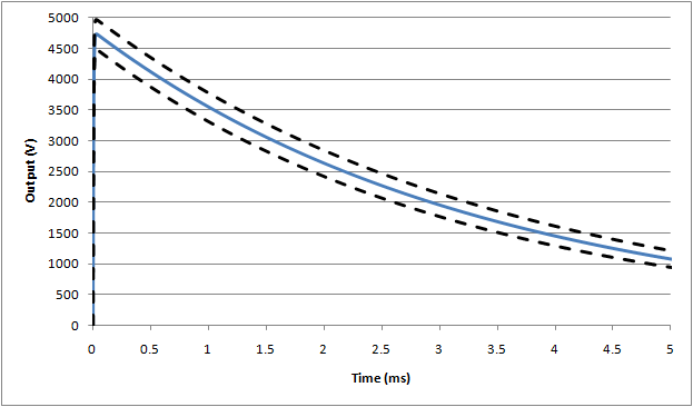

Waveform #1: 500µH (full waveform), nominal assumes 5Ω inductor resistance
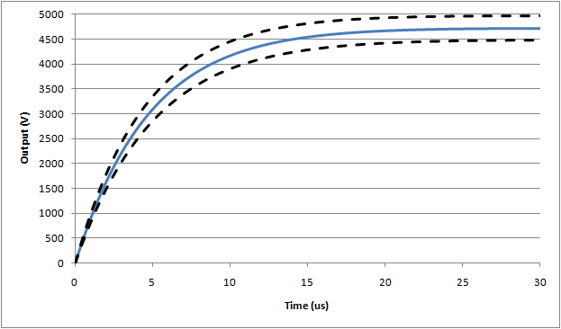

Waveform #1: 500µH (expanded rise time), nominal assumes 5Ω inductor resistance
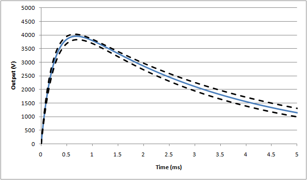
 
Waveform #3: 25mH (full waveform)

 If, as can be expected, actual waveforms do not comply within these limits, the following extenuating circumstances may be considered: if the rise time and peak values are higher than expected (likely due to problems with the series inductor), this waveform can be considered as being more stressful than the requirements in the standard. Since the design of equipment is not expected to fail, equipment that passes under higher rise time/voltage conditions can be considered as complying with the standard.

For the operator energy circuit, the circuit can be tested by replacing the device under test with a resistor. Using simulations (including the effect of the diodes), the following resistor values yield:

100.0kΩ     ⇒  Y1-Y2 = 1.38V
135.6kΩ     ⇒  Y1-Y2 = 1.00V
141.0kΩ     ⇒  Y1-Y2 = 0.96V
150.0kΩ     ⇒  Y1-Y2 = 0.90V

 The 141kΩ can be made up of 3 series 47kΩ, 0.25W standard metal film resistors. The expected energy per pulse is only 85mW/resistor. If other types of resistors are used, ensure they are suitably non-inductive @ 100kHz.

Since there are several components in this circuit, and taking into account the nature of the test, outputs within 15% of the expected value can be considered to be calibrated.

[End of material]


IEC 60601-1 Clause 4.5 Alternate solutions

This clause is intended to allow manufacturers to use alternate methods other than those stated in the standard.

In Edition 3.0 of IEC 60601-1, Clause 4.5 was titled "Equivalent Safety" and the criteria stated as "the alternative means [having] equal to or less than the RESIDUAL RISKS that result from applying the requirements of this standard".

In Edition 3.1 the title was changed to "Alternative ... measures or test methods" and the criteria to a "...  measure or test method [that] remains acceptable and is comparable to the RESIDUAL RISK that results from applying the requirements of this standard."

The change was most likely required as standards often use worst case assumptions in order to cover a broad range of situations. The result is that for an individual medical device, the requirement is really massive overkill for the risk. The original version required the alternate solution to reach for the same level of overkill, which made little sense. 

In practice, this works if both the standard solution and the alternate solution have negligible risk. In the real world, risk profiles often have a region of significant risk which then transitions to a region of negligible risk. For example, a metal wire might be required to support 10kg weight. If we consider using wire with 10-30kg capacity there is still some measurable probability of mechanical failure. But if we step out a bit further we find that the probability numbers become so small that it really does not matter whether you use 50kg or 200kg wire. Theoretically, a 200kg rating is safer than 50kg, but either solution can be considered as having negligible risk. 

In that context, the standard works well. 

But there are two more difficult scenarios to consider.

The first is that due to technology, competition, commercial issues or whatever, the manufacturer does not want to meet a particular requirement in a standard. The alternate solution has some non-negligible risk which is higher than the solution in the standard, but deemed acceptable according to their risk management scheme.

Clearly, Clause 4.5 is not intended for this case. Instead, manufacturers should declare that they don't meet the particular requirement (either "Fail" or "N/E" in a test report) and then deal with the issue as is allowed in modern medical device regulation. It is often said that in Europe standards are not mandatory - which is true but there is a catch, you need to document your alternate solution against the relevant essential requirement. The FDA has similar allowance, as has most countries. 

Obviously, manufacturers will push to use 4.5 even when significant risk remains, to make a clean report and avoid the need to highlight an issue to regulators. In such a case, test labs should take care to inspect if the alternate solution really has negligible risk, or just acceptable risk.

The second scenario is when the standard has an error, unreasonable requirement or there is a widespread interpretation such as allowing UL flammability ratings in place of IEC ratings. For completeness it can be convenient to reach for Clause 4.5 as a way to formally fix these issues in the standard. In practice though it can crowd the clause as standards have a lot of issues that need to be quietly fixed by test labs. It is probably best to use a degree of common sense rather than documenting every case.  

Finally it should be noted that it is not just a matter of arguing that a requirement in the standard is unreasonable for a particular medical device. Manufacturers should also consider the alternate solution - for example a manufacturer might argue that IPX2 test in IEC 60601-1-11 for home use equipment is overkill. Even if this is reasonable, it does not mean the manufacturer can ignore the issue altogether. It should be replaced by another test which does reflect the expected environment of use, such as 30s rain test at 1mm/min. 

IEC 60601-1 Clause 4.4 Service Life

It is a common assumption that service life should be derived from the properties and testing of the actual medical device. This view is even supported by ISO TR 14969 (guidance on ISO 13485), which states in Clause 7.1.3 that the "... basis of the defined lifetime of the medical device should be documented" and goes on to suggest items to consider.

Fortuntely this view is wrong, and is an example of the blinkered view that can sometimes occur from different medical fields. For some simple medical devices, it is feasible to consider lifetime as an output of the design process, or the result of consideration of various factors. But that's far from true for complex electronic medical devices such as those often covered by IEC 60601-1.

The correct interpretation (regardless of the type of medical device), is that lifetime is simply something which is decided by the manufacturer, and there is no regulatory requirement to document the basis of the number chosen.

It is a requirement that the lifetime must be declared and documented. IEC 60601-1 Clause 4.4 simply asks that this is stated in risk management file.

And, having declared this lifetime, the manufacturer must then go on to show that risks are acceptable over the life of the device.

For some medical devices, lifetime will be an important factor in many risk related decisions, such as sterility, mechanical wear and tear and materials which degrade over time. 

For other medical devices, lifetime hardly gets a thought in the individual risk controls.

Why?

For electrical devices we are a little different in our approach. These days, modern electrical parts last for much (much) longer than the lifetime of the product. And there are thousands of parts in a single product. Inevitably there will be the odd part here and there that breaks down earlier than others, but on a component basis it very rare and hard to predict.

Secondly, we rarely entrust high risk stuff to a single part. We assume that things fail from time to time, and implement protection systems to prevent any serious harm.

There can be cases where lifetime does play a role, but it is the exception rather than the rule. Even then, it would be rare that the lifetime of a part or risk control drives the overall decision on the medical device lifetime. Us electrical engineers don't push things to the edge like that. The risk management might determine that a particular critical part needs a failure rate of less than 1 in 10,000 over the 5 year lifetime of the device. So, we pick a part with 1 in 1,000,000 in 10 years. It's just a different way of thinking in electronic design.

So the next time an auditor asks you how you derived the lifetime of your incredibly complex X-ray machine based on as risk, quietly direct them the marketing department.

IEC 60601-1 Clause 4.3 Essential Performance

The basic idea behind essential performance is that some things are more important than others. In a world of limited resources, regulations and standards should try to focus on the important stuff rather than cover everything. A device might have literally 1000’s of discrete “performance” specifications, from headline things such as equipment accuracy through to mundane stuff like how many items an alarm log can record. And there can be 100’s of tests proving a device meets specifications in both normal and fault condition: clearly it’s impossible check every specification during or after each one of these tests. We need some kind of filter to say OK, for this particular test, it’s important to check specifications A, B and F, but not C, D, E and G.

Risk seems like a great foundation on which to decide what is really “essential”. But is it a complicated area, and the “essential performance“ approach in IEC 60601-1 is doomed to fail as it oversimplifies it to a single rule: "performance ... where loss or degradation beyond the limits ... results in an unacceptable risk".

A key point is that using acceptable risk as the criteria is, well, misleading. Risk is in fact the gold standard, but in practice it gets messy because of a bunch of assumptions hiding in the background. Unless you are willing to tease out these hidden assumptions, it’s very easy to get lost. For example, most people would assume that the correct operation of an on/off switch does not need to be identified as “essential performance”. Yet if the switch fails, the device then fails to treat, monitor or diagnose as expected, which is a potential source of harm. But your gut is still saying … nah, it doesn’t make sense - how can an on/off switch be considered essential performance? The hidden assumption is that the switch will rarely fail - instinctively we know that modern switches are sufficiently reliable that they are not worth checking, the result of decades of evolution in switch design. And, although there is a potential for harm, the probability is generally low: in most cases the harm is not immediate and there is time to get another device. These two factors combined are the hidden assumptions that - in most cases - means that simple on/off switch is not considered essential performance.

In practice, what is important is highly context driven, you can't derive this purely from the function. Technology A might be susceptible to humidity, technology B to mechanical wear, technology C might be so well established that spot checks are reasonable. Under waterproof testing, function X might be important to check, while under EMC test function Y is far more susceptible.

Which means that simply deriving a list of what is "essential performance" out of context makes absolutely no sense.

In fact, a better term to use might be "susceptible performance", which is decided and documented on a test by test basis, taking into account:

  • technology used (degree to which it well established, reliable)

  • susceptibility of the technology to the particular test

  • the relationship between the test condition and expected normal use (e.g. reasonable, occasional, rare, extreme)

  • the severity of harm if the function fails

Note this is still fundamentally risk based: the first three parameters are associated with probability, and the last is severity. That said, it is not practical to analyse the risk in detail for each parameter, specification or test: there are simply too many parameters and most designs have large margins so that there are only a few areas which might be sensitive in a particular test. Instead, we need to assume the designer of the device is sufficiently qualified and experienced to know the potentially weak points in the design, as well as to develop suitable methods including proxies to detect if a problem has occurred. Note also that IEC 60601-1 supports the idea of “susceptible performance” in that Clause 4.3 states that only functions/features likely to be impacted by the test need to be monitored. The mistake is that the initial list of “essential performance” is done independently of the test.

The standard also covers performance under abnormal and fault condition. This is conceptually different to “susceptible performance” as it is typically not expected that devices continue to perform according to specification under abnormal conditions. Rather, manufacturers are expected to include functions or features that minimise the risk associated with out-of-specification use: these could be called “performance RCMs”: risk control measures associated with performance under abnormal conditions. A common example is a home use thermometer, which has a function to blank the temperature display when the battery falls to levels that might impact reliable performance. Higher risk devices may use system monitoring, independent protection, alarms, redundant systems and even back up power. Since these are risk control measures, they can be referenced from the risk management file and assessed independently to “susceptible performance”. Performance RMS can be tricky as it pulls into focus the issue of what is “practical”: many conditions are easy to detect, but many others are not; those that are not detected may need to be written up as risk/benefit if the risk is significant.

Returning to “susceptible performance”, there are a few complications to consider:  

First is that "susceptible performance" presumes that, in the absence of any particular test condition, general performance has already been established. For example, a bench test in a base condition like 23°C, 60% RH, no special stress conditions (water ingress, electrical/magnetic, mechanical etc.). Currently in IEC 60601-1 there is no general clause which establishes what could be called "basic performance" prior to starting any stress tests like waterproof, defib, EMC and so on. Even now, this is a structural oversight in the standard, since it allows the test to focus on parameters that are likely to be affected by the test, which only makes sense if the other parameters have already been confirmed.

Second is that third party test labs are often involved and the CB scheme has set rules that test labs need to cover everything. As such there is reasonable reluctance to consider true performance for fear of exposing manufacturers to even higher costs and test labs thrown into testing they are not qualified to perform. This needs to be addressed before embedding too much performance in IEC 60601-1. Either we need to get rid of test labs (not a good idea), or structure the standards that allows test labs to separate out those generic tests they are competent to perform from specialised tests, as well as practical ways in which to handle those specialised aspects when then cross over into generic testing (such as an IPX1 test).

Third is that for well established technology (such as diagnostic ECGs, dialysis, infusion pumps) it is in the interests of society to establish standards for performance. As devices become popular, more manufacturers will get involved; standardisation helps users be sure of a minimum level of performance and protects against poor quality imitations. This driver can range from very high risk devices through to mundane low risk devices. But the nature of standards is such that it is very difficult to be comprehensive: for example, monitoring ECG have well established standards with many performance tests, but many common features like ST segment analysis are not covered by IEC 60601-2-27. The danger here is using defined terms like “essential performance” when a performance standard exists can mislead people to think that the standard covers all critical performance, when in fact it only covers those aspects that have been around long enough to warrant standardisation.

Finally, IEC 60601-1 has special requirements for PEMS for which applicability can be critically dependent on what is defined as essential performance. These requirements can be seen as special design controls, similar to what would be expected for Class IIb devices in Europe. They are not appropriate for lower risk devices, and again using the criteria of “essential performance” to decide when they are applicable creates more confusion.

Taking these into account, it is recommended to revert a general term "performance", and then consider five sub-types:

Basic performance: performance according manufacturer specifications, labelling, public claims, risk controls or can be reasonably inferred from the intended purpose of the medical device. Irrespective of whether there are requirements in standards, the manufacturer should have evidence of meeting this basic performance.

Standardised performance: requirements and tests for performance for well established medical devices published in the form of a national or international standard. 

Susceptible performance: subset of basic and/or standardised performance to be monitored during a particular test, decided on a test by test basis, taking into account the technology, nature of test, severity if a function fails and other factors as appropriate, with the decisions and rationale documented or referenced in the report associated with the test.

Critical performance: subset of basic and/or standardised performance performance which if fails, can lead to significant direct or indirect harm with high probability; this includes functions which provide or extract energy, liquids, radiation or gases to the patient in a potentially harmful way; devices which monitor vital signs with the purpose of providing alarms for emergency intervention, and other devices with similar risk profile (Class IIb devices in Europe can be used as a guide). Aspects of critical performance are subject to additional design controls as specified in Clause 14 of IEC 60601-1  

Performance RCMs: risk controls measures associated with performance under abnormal conditions, which may include prevention by inherent design (such as physical design), prevention of direct action (blanking display, shut off output), indication, alarms, redundancy as appropriate.

Standards should then be structured in a way that allows third party laboratories to be involved without necessarily taking responsibility for performance evaluation that is outside the laboratories competence.

IEC 60601-1 Clause 4.2 - Risk Management

The ability to apply flexibility in certain places of a standard makes a lot of sense, and the risk management file is the perfect place to keep the records justifying the decisions.

Yet, if you find risk management confusing in real application, you are not alone. The reason is not because you lack skills or experience – instead embedding risk management in IEC 60601-1 is a fundamental mistake for three reasons.

First is simple logistics. The correct flow is that the risk management file (RMF) studies the issue, and proposes a solution. That solution then forms a technical specification which can be evaluated as part of a product standards like IEC 60601-1, particularly those places where the standard allows or requires analysis. When the verification tests are successful, a report is issued. The RMF can be completed and the residual risk judged as acceptable. This forms a kind of mini V-model:

Embedding risk management in a product standard creates a circular reference which can never solved - the RMF cannot be signed off until the product report is signed off, the product report cannot be signed off until the RMF is signed off. This is more than just a technicality – it debases and devalues the risk management by forcing manufacturers to sign off early, especially when test labs are involved.

Which leads us to our second problem: Third party test laboratories are valuable resource for dealing with key risks such as basic electrical safety and EMC. But they are ill equipped to deal with subjective subjects, and ISO 14971 is whopper in the world of subjectivity: everyone has their own opinion. The V-model above isolates the product standard (and third party test labs) from the messy world of risk management.

Which brings us to our third problem – the reason why risk management is so messy. Here we find that ISO 14971 that has its own set of problems. First, there are in practice too many risks (hazardous situations) to document in a risk management file: the complexity of a medical device design, production process, shipping, installation, service, interfaces between the device and the patient, operator and the environment contain tens of thousands situations that have genuine risk controls. ISO 14971 fails to provide a filter for isolating out those situations worth documenting.

Secondly is the rather slight problem that we can’t measure risk. Using risk as the parameter on which decisions are made is like trying to control the temperature of your living room using a thermometer with an accuracy of ±1000°C. Our inability to measure risk with any meaningful accuracy leads to a host of other problems to long to list here.

Yet In the real world we efficiently handle tens of thousands of decisions in the development and production processes that involve risk - it’s only the relatively rare case that we get it wrong.

The answer may lie in “risk minimum theory”, which is planned to be detailed further on this site at a later date. This theory provides a filter function to extract only the risks (hazardous situations) worth investigating and documenting in the risk management file, also provides a way to make risk related decisions without measuring risk. 

In the mean time, we need to deal with ISO 14971. This article recommends:

  • Don’t panic – everybody is confused!

  • Follow the minimum requirements in the standard. Even if you don’t agree or it does not make sense, make sure every document or record that is required exists, and that traceability (linking) is complete. Use a checklist showing each discrete requirement in ISO 14971 and point to where the your records exist for that requirement. Keep in mind that the auditors and test engineers didn’t write the standard, but they have to check implementation, so following the standard - even if blindly - helps everyone.

  • Watch carefully for the places where the standard says a record is needed, and where verification is needed. There is a difference – a “record” can be as simple as a tick in a box or a number in a table, without justification. “Verification” means keeping objective evidence. Verification is only required in selected places, which may be a deliberate decision by the authors to try and limit overkill.

  • Develop your own criteria for filtering what goes in in the file. The risk minimum theory concludes that that risk controls which are clearly safe, standard practice, and easy for a qualified independent person to understand by inspection do not need to be in the file. Risk controls that are complex, need investigation to know the parameters, borderline safety or balanced against other risks should be documented.

  • As an exception to the above, keep a special list of requirements in product standards like IEC 60601-1 that specifically refer to risk management, including a formal judgement if they are applicable (or N/A), and a pointer to the actual place in the risk management file where the item it handled. Again this helps everyone – manufacturer, auditors and test engineers

  • Be aware that there are three zones in safety: the green and red zones, where there is objective evidence that something is either safe or unsafe, and a grey zone in between where there is no hard evidence either way. In the real world, 99% of risk controls put us in the green zone; but there are still 10-100 that inevitably fall in the grey zone.

  • If you are in this grey zone, watch out for the forces that influence poor risk management decisions: conflicts of interest, complexity, new technology, competition, cost, management pressure and so on. Don’t put a lot of faith in numbers for probability, severity, risk or criteria, be aware of camouflage - a warning in a manual magically reducing the risk by 2 orders of magnitude, masking the real risk control. Dig deeper, find the real risk control, and then decide if it is reasonable.


IEC 60601-1 and accessories

These days many medical applications are a system comprising of a main unit and accessories or detachable parts.

Under medical device regulations, it is allowed for each part of a system to be treated as an individual medical device. Despite some concerns, regulations do not require any contract or agreement between the different manufacturers making up parts of the system. 

Instead, they rely on risk management, which is appropriate given wide range of situations and regulatory issues. For example, labelling, instructions, sterilisation and bio-compatibility are reasonably under the responsibility of the accessory manufacturer. Electrical isolation from mains parts, EMC emissions and immunity are normally under the responsibility of the main unit manufacturer. In some cases there are shared system specifications (such as system accuracy shared between main unit and sensor), in other cases there are assumptions based on reasonable expectations or industry norms (such as IBP sensor insulation). In the end the analysis should resolve itself into interface specifications which allocate some or all of the system requirements to either the main unit or the accessory. 

There is a valid concern that by keeping the analysis by each manufacturer independent, critical issues could fall through the cracks. Each manufacturer could assume the other will handle a particular requirement. And sometimes system requirements are difficult to separate. 

Even so, the alternative is unthinkable: a system only approach only works if there are agreements and constant exchange of information between the different manufacturers in a system.  This would create an unwieldy network of agreements between tens of thousands of manufacturers throughout the world, difficult to implement, virtually impossible to maintain. While regulators surely recognise the concern, the alternative is far worse. Thus it remains in the flexible domain of risk management to deal with practical implementation. 

IEC 60601-1 makes a mess of the situation, again highlighting the lack of hands on regulatory experience in those involved with developing the standard.

The definition of "ME equipment" in Clause 3.63 has a "Note 1" which states that accessories necessary for normal use are considered part of the ME equipment. The standard also has many requirements for accessories, such as labelling, sterilisation and mechanical tests. This implies a system only approach to testing. 

Yet the standard trips up in Clause 3.55, by defining a "manufacturer" as the "person with responsibility for ... [the] ME equipment".

Both of these definitions cannot be true, unless again we have an impossible network of agreements between all the manufacturers of the different parts of the overall system.

Clause 3.135 also defines a "Type Test" as a "test on a representative sample of the equipment with the objective of determining if the equipment, as designed and manufactured, can meet the requirements of this standard". 

Again, this definition can only be met if the manufacturer of the accessory is contractually involved, since only the accessory manufacturer can ensure that a type test is representative of regular production, including the potential for future design changes.  

What's the solution?

An intermediate approach is to first recognise that the reference to accessories in Clause 3.63 is only a "note", and as the preamble to all IEC standards indicates, "notes" written in smaller type are only "informative". In other words, the note is not a mandatory part of the standard. 

Secondly, it is possible that the writers of the standard never intended the note to mean the standard must cover accessories from other manufacturers. Rather, the intention was probably to highlight (note) that in order to run the various tests in the standard accessories would be needed to establish normal condition. The note is a clumsy way of avoiding that manufacturer insists the tests are done without any regard to the accessories.

A longer term solution would be to add a new clause in the standard (e.g. 4.12) which requires an analysis of accessories from other manufacturers to:

  • Allocate system requirements to either the main unit or accessory, either in part or in full

  • Document a rationale behind the selection of representative accessories to establish normal condition during tests on the main unit

  • Document a rationale to identify accessories in the instructions for use: either directly by manufacturer and type, or indirectly by specification

The following is an example analysis for a patient monitor with a temperature monitoring function (for illustration only):

This analysis should be included in or referenced from the risk management file.

The analysis might appear onerous, but the ability to stream line type testing will save time in the long run, and allow common sense apply. In the current approach, decisions about accessories are made on the run, and can result in both over and under testing.

Manufacturers are also reluctant to mention accessories in the operation manual, partly due to the logistics of keeping the manual up to date, and partly due to a fear of being seen to be responsible for the accessories listed. This fear often extends to the design documentation including the risk analysis, with virtually no mention accessories in the files. The above approach helps to address the fear while at the same time highlighting that accessories can't be simply ignored. A rationale for the requirements, representative selection and documentation to the user is both reasonable and practical.   

The recommendations above cover a simple system of an main unit designed by manufacturer "X" working a sensor designed by manufacturer "Y". There exists another more complicated scenario, where part of the electronics necessary to work with the accessory provided by manufacturer Y is installed inside the main unit from manufacturer X. A common example is an OEM SpO2 module installed inside a patient monitor. Technically, manufacturer X takes responsibility for this "interface module" as it falls under their device label. In such a case, a formal agreement between X and Y is unavoidable. Once this agreement is in place, the same risk analysis for the three points above should apply.

In this special case, a type test also needs some consideration. In general it is not practical for manufacturer of the main unit to support testing for the module, as it usually requires the release of a large amount of information much of which would be confidential. Instead, the laboratory should look for test reports from manufacturer B for the interface module, essentially as a "component certification" similar to an recognised power supply. Another option would be for the report to report to exclude requirements on the presumption that these will be handled by the module/accessory manufacturer, as per the inter-company agreement. The module manufacturer would then have their internal reports to cover the excluded clauses. In case of product certification and CB scheme, some exclusions may not be allowed, in which case the module is best covered by a CB certificate to allow simple acceptance by the laboratory responsible for the main device. 

Finally, there is a bigger role that standard can play to help avoid gaps in responsibility - the development of standards for well established accessories which define clearly which manufacturer should cover which requirements. Such standards already exist at the national level, for example ANSI/AAMI BP 22 for IBP sensors. A generic standard could also be developed which handles accessories not covered by a particular standard, which highlights risk analysis and declaration of assumptions made. 

It's time that the IEC 60601 series was better aligned with modern regulations and reality: accessories are a separate medical device.    

IEC 60601-1 Amendment 1 Update Summary

Overview

Amendment 1 to IEC 60601-1:2005 was released in July 2012 and is now becomming main stream for most regulations. This article, originally published in 2013 summarises the changes

The basic statistics are:

  • 118 pages (English)
  • 67 pages of normative text
  • ~260 changes
  • 21 new requirements
  • 63 modifications to requirements or tests
  • 47 cases where risk management was deleted or made optional
  • 19 corrections to requirements or test methods
  • Remainder were reference updates, notes, editorial points or clarifications
  • USD$310 for amendment only
  • USD $810 for the consolidated edition (3.1)

This document covers some of the highlights, including an in-depth look at essential performance. A pdf version of this analysis is avaliable, which also includes a complete list of the changes on which the analysis is made.

Highlights

Risk management has been tuned up and toned down: the general Clause 4.2 tries to makes it clear that for IEC 60601-1, the use of ISO 14971 is really about the specific technical issues, such as providing technical criteria for a specific test or justifying an alternate solution. Full assessment of ISO 14971 is not required, and post market area is specifically excluded. The standard also clearly states that an audit is not required to determine compliance.

Within the standard, the number of references to risk management have been reduced, with some cases of simply reverting back to the original 2nd edition requirements.  In other places, the terminology used in risk management references has been corrected or made consistent. 

Essential performance has quietly undergone some massive changes, but to understand the impact of the changes you need to look at several aspects together, and some lengthy discussion is warranted.

First, the standard requires that performance limits must be declared. In the past a manufacturer might just say “blood pump speed” is essential performance, but under Ed 3.1 a specification is also required e.g. “blood pump speed, range 50-600mL/min, accuracy ±10% or ±10mL of setting, averaged  over 2 minutes, with arterial pressure ±150mmHg, venous pressure -100~+400mmHg, fluid temperature 30-45°C”.

Next, the manufacturer should consider separately essential performance in abnormal or fault conditions. For example under a hardware fault condition a blood pump may not be expected to provide flow with 10% accuracy, but it should still confidently stop the blood flow and generate a high priority alarm. Care is needed, as the definition of a single fault condition includes abnormal conditions, and many of these conditions occur at higher frequency than faults and therefore and require a special response. User errors, low batteries, power failure, use outside of specified ranges are all examples where special responses and risk controls may be required that are different to genuine fault condition. For example, even a low risk diagnostic device is expected to stop displaying measurements if the measurement is outside of the rated range or battery is too low for accurate measurement. Such risk controls are now also considered “essential performance”.

Essential performance must also be declared in the technical description. This is major change since it forces the manufacturer to declare essential performance in the commercial world, especially visible since most manufacturers incorporate the technical description in the operation manual. Until now, some manufacturers have declared there is no essential performance, to avoid requirements such as PEMS. But writing “this equipment has no essential performance” would raise the obvious question … what good then is the equipment?

Finally many of the tests which previously used basic safety or general risk now refer specifically to essential performance in the test criteria. In edition 3.0 of the general standard, the only test clause which specifically mentioned essential performance was the defibrillator proof tests. Now, essential performance is mentioned in the compliance criteria many times in Clauses 9, 11 and 15. These are stress tests including mechanical tests, spillage, sterilization and cleaning.  The good news is that the standard makes it clear that functional tests are only applied if necessary. So if engineering judgment says that a particular test is unlikely to impact performance, there is no need to actually test performance.

While essential performance is dramatically improved there are still two areas the standard is weak on. First, there is no general clause which requires a base line of essential performance to be established. Typically, performance is first verified in detail under fairly narrow reference conditions (e.g. nominal mains supply, room 23±2°C, 40-60%RH, no particular stress conditions). Once this base line is established, performance is then re-considered under a range of stress conditions representing normal use (±10% supply voltage, room temperature 10-40°C, high/low humidity, IP tests, mechanical tests, cleaning test, and so on). Since there are many stress tests, we normally use engineering judgment to select which items of performance, if any, need to be re-checked, and also the extent of testing. But this selective approach relies on performance having been first established in the base-line reference condition, something which is currently missing from the general standard.

The second problem is the reference to essential performance in PEMS (Clause 14). Many low risk devices now have particular standards with essential performance. And since essential performance is used as a criteria for stress tests, the “no essential performance” approach is no longer reasonable. But the application of complex design controls for lower risk devices is also unreasonable, and conflicts with modern regulations. Under note 2, the committee implies that Clause 14 needs only to be applied to risk controls. A further useful clarification would be to refer to risk controls that respond to abnormal conditions. For example, in a low risk device, the low battery function might be subject to Clause 14, but the main measurement function should be excluded, even if considered “essential performance”. It would be great if the committee could work out a way to ensure consistent and reasonable application for this Clause.

Moving away from essential performance to other (more briefly discussed) highlights are:

  • Equipment marking requirements: contact information, serial number and date of manufacture are now required on the labeling, aligning with EU requirements. The serial number is of special note, since the method of marking method is often different to the main label, and may not be as durable.
     
  • Accessories are also required to marked with the same details (contact information, serial number, date of manufacturer). This also fits with EU requirements, provided that the accessory is placed on the market as a separate medical device. This may yield an effective differentiation between an “accessory” and a “detachable part”. The new requirement implies that accessories are detachable parts which are placed on the market (sold) separately, whereas detachable parts are always sold with the main equipment.
     
  • Both the instructions for use and the technical description must have a unique identifier (e.g. revision number, date of issue)
     
  • For defibrillator tests, any unused connectors must not allow access to defibrillator energy (effectively requires isolation between different parts, or special connectors which prevent access to the pins when not in use)
     
  • Mechanical tests for instability and mobile equipment (rough handling test) are modified (market feedback that found the tests to be impractical)
     
  • The previous 15W/900J exemption of secondary circuits from fire enclosure/fault testing has been expanded to 100VA/6000J if some special criteria are met. Since the criteria are easy to meet, it will greatly expand the areas of the equipment that does not need a fire enclosure or flame proof wiring; welcome news considering the huge environmental impact of flame retardants.
     
  • For PEMS, selected references to IEC 62304 are now mandatory (Clauses 4.3, 5, 7, 8 and 9)

For a complete (unchecked) list of changes, including a brief description and a catergory of the type of change, please refer to the pdf version.  

For comments and discussion, please contact peter.selvey@medteq.jp.