IEC 60601-2-2 Dielectric heating

This article has been transferred from the original MEDTEQ website with minor editorial update.

~~~~~~~~~~~~~~~~~~~~~~~~~~~~~~~~~~~~~~~~~~~~~~~~~~~

The mechanism of breakdown at high frequency is different to normal mains frequency dielectric strength tests - it can be thermal, rather than basic ripping apart of electrons from atoms. Also, for mains frequency tests, there tends to be a large margin between the test requirement and what the insulation can really handle, meaning that errors in the test method are not always critical. In contrast, the margin for HF insulation can be slight, and the test method can greatly affect the test result.

HF burns, in part due to insulation failure, continue to be a major area of litigation. Of particular concern is the high fatality rate associated with unintentional internal burns which may go unnoticed.

For those involved in designing or testing HF insulation, it is absolutely critical to have a good understanding of the theory behind HF insulation and what causes breakdown. This article looks into the detail of one of those mechanisms: thermal effects. 


Theory

All insulating materials behave like capacitors. With an ac voltage applied, some current will flow. At 230V 50/60Hz, this amount of current is very small, in the order of 20uA between conductors in a 2m length of mains cable. But at 300-400kHz, the current is nearly 10,000 times higher, easily reaching in the order of 10mA at 500Vrms, for just short 10cm of cable.  

All insulating materials will heat up due to the ac electric field. This is called dielectric heating or dipole heating. One way to think of this is to consider the heating to be due to the friction of molecules moving in the electric field. Microwave ovens use this property to heat food, and dielectric heating is used also in industrial applications such as welding plastics. These applications make use of high frequency, usually in the MHz or GHz range.

At 50-60Hz the amount of heating is so small it amounts to a fraction of a fraction of a degree. But again at 300-400kHz the amount of heating can be enough to melt the insulation.

The temperature rise caused by dielectric heating can be estimated from:

dT = 2π V2 f ε0εr d t / H D d2      (K or °C)

Although this is a rather complicated looking formulae, it is mostly made up of material specific parameters that can be found with some research (more details on this are provided below). To get some feel for what this means, let's put this in a table where voltage and thickness are varied, for a frequency of 400kHz, showing two common materials, PVC and Teflon:

Predicted insulation temperature rise @ 400kHz


Voltage PVC Insulation Thickness (mm)
(Vrms) 1 0.8 0.6 0.4 0.2
  Temperature rise (K)
200 0.7 1.1 1.9 4.3 17.3
400 2.8 4.3 7.7 17.3 69.3
600 6.2 9.7 17.3 39.0 156.0
800 11.1 17.3 30.8 69.3 277.3
1000 17.3 27.1 48.1 108.3 433.3
1200 25.0 39.0 69.3 156.0 623.9


 Table #1: Because of a high dissipation factor (d = 0.016), PVC can melt at thicknesses commonly found in insulation. 
For broad HF surgical applications, a thickness of at least 0.8mm is recommended 


Voltage Teflon Insulation Thickness (mm)
(Vrms) 0.5 0.3 0.1 0.05 0.03
  Temperature rise (K)
200 0.0 0.1 0.5 2.1 5.9
400 0.1 0.2 2.1 8.5 23.7
600 0.2 0.5 4.8 19.2 53.4
800 0.3 0.9 8.5 34.2 94.9
1000 0.5 1.5 13.3 53.4 148.3
1200 0.8 2.1 19.2 76.9 213.5


 Table #2: Teflon has a far lower dissipation factor (less than 0.0002), so even 0.1mm is enough for broad HF surgical applications. 
However, because of Teflon's superior qualities and high cost, insulation thickness is often reduced to around the 0.1mm region

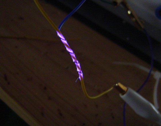
For PVC insulation, these predicted values match well with experimental tests, where a small gauge thermocouple was used as the negative electrode and the temperature monitored during and after the test. For insulation with thickness varying between 0.3mm and 0.5mm, temperatures of over 80°C were recorded at voltages of 900Vrms 300kHz, and increasing the voltage to 1100Vrms resulted in complete breakdown.


Practical testing

As the formulae indicates, the temperature rise is a function of voltage squared, and an inverse function of thickness squared. This means for example, if the voltage is doubled, or the thickness is halved, the temperature rise quadruples. Even smaller variations of 10-20% can have a big impact on the test result due the squared relation.

Because insulation thickness varies considerably in normal wiring, it is possible that one sample may pass while another may not. Although IEC 60601-2-2 and IEC 60601-2-18 do not require multiple samples to be tested, good design practice would dictate enough samples to provide confidence, which in turn depends on the margin. For example, if your rated voltage is only 400Vrms, and your thickness is 0.8+/- 0.2mm, then high margin means the test is only a formality. On the other hand, if your rating is 1200Vrms, and the thickess if 0.8+/-0.2mm, perhaps 10 samples would be reasonable.

Test labs need to take care that the applied voltage is accurate and stable, which is not an easy task. Most testing is performed using HF surgical equipment as the source, however, these often do not have a stable output. Also, the measurement of voltage at HF is an area not well understood. In general, passive HV probes (such as 1000:1 probes) should not be used, since at 400kHz these probes operate in a capacitive region in which calibration is no longer valid (see here for more discussion) and large errors are common. Specially selected active probes or custom made dividers which have been validated at 400kHz (or the frequency of interest) are recommended.   

Perhaps the biggest impact to the test result is heat sinking. The above formulae for temperature rise assumes that all the heat produced cannot escape. However, the test methods described in IEC 60601-2-2 and IEC 60601-2-18 do not require the test sample to be thermally insulated. This means, some or most of the heat will be drawn away by the metal conductors on either side of the insulation, by normal convection cooling if the sample is tested in an open environment, or by the liquid if the sample immersed in fluid or wrapped in a saline soaked cloth.  

This heat sinking varies greatly with the test set up. The test in IEC 60601-2-2 (wire wrap test) is perhaps the most severe, but even something as simple as the test orientation (horizontal or vertical) is enough to substantially affect the test result.

Because of these three factors (variations in insulation thickness, applied voltage, heatsinking) bench testing of HF insulation should only be relied on as a back up to design calculations. Test labs should ask the manufacturer for the material properties, and then make a calculation whether the material is thermally stable at the rated voltage and frequency. 

The above formulea is again repeated here, and the following table provides more details on the parameters needed to estimate temperature rise. The temperature rise should be combined with ambient (maybe 35°C for the human body) and then compared to the insulation's temperature limit.


dT = 2π V2 f ε0εr d t / H D d2      (K or °C)


Symbol  Parameter Units Typical value Notes
V Test voltage Vrms 600 - 1200Vrms

Depends on rating and test standard. Note that ratings with high peak or peak to peak values may still have moderate rms voltages. Under IEC 60601-2-2, a rating of 6000Vp would require a test with 1200Vrms. 
 

f Test frequency  Hz 300-400kHz Depends on rating. Monopolar HF surgical equipment is usually less than 400kHz1 
ε0 Free space permittivity  F/m 8.85 x 10⁻¹² Constant
εr Relative permittivity  unit less ~2 Does not vary much with materials
δ Dissipation factor unit less 0.0001 ~ 0.02 Most important factor, varies greatly with material. Use the 1MHz figures (not 1kHz)
t Test time s 30s IEC 60601-2-2 and IEC 60601-2-18 both specify 30s
H Specific heat J/gK 0.8 ~ 1 Does not vary much with materials
D Density  g/cm3 1.4 ~ 2 Does not vary much with materials
d Insulation thickness mm 0.1 ~ 1 Based on material specification. Use minimum value


 1Dielectric heating also occurs in bipolar applications, but due to the significantly lower voltage, the effect is much less significant.   

IEC 60601-2-2 201.8.8.3 High Frequency Dielectric Strength

Experience indicates there are two main causes for insulation failure at high frequency: thermal and corona. Both of these are influenced by the higher frequency of the test waveform and the effects may not be well appreciated for the test engineer more familiar with mains frequency testing. 

Thermal

In addition to high voltage, electrosurgery devices also operate at a relatively high frequency of around 400kHz. At this frequency, surprisingly high currents can flow in the insulation - roughly 8,000 times higher than those at mains frequency. For example, a 50 cm length of cable immersed in saline solution tested at 1000Vrms/400kHz can easily have over 200mA flowing through the insulation, creating a sizeable 200VA load.

Although this VA load is predominately reactive or apparent power (var), insulators are not perfect and a portion will appear as real power in watts. This is determined by the dissipation factor (δ) of the material. Some materials like PVC have a high factor (δ around 0.01-0.03), which means that 1-3% of the total VA load will appear as heat. In the example above, if the test sample was PVC insulation with δ = 0.02, it means the test would create 4W of heat (200VA x 0.02). That heat can be enough to melt the insulation, causing dielectric breakdown.

The theory is discussed in more detail in this article from the original MEDTEQ website. As the article indicates, key factors are:

  • the rms test voltage, with heat is proportional to Vrms squared

  • thickness of the insulation, with heat inversely proportional to thickness squared

  • material dissipation factor

  • the test set up (availability of heatsinks such as liquids, electrodes)

While it is obvious the authors of IEC 60601-2-2 are aware of the thermal effects, the test in the standard seems to be poorly designed considering these factors. First, the standard concentrates on peak voltage and has a fairly weak control of the rms voltage. Secondly it is expected that thickness is not constant, so testing multiple samples may make sense, particularly for thin insulation. And thirdly the heatsink effect of the set up should be carefully considered. 

In critical situations, good manufacturers will opt for low dissipation factor materials such as Teflon, which has δ ~ 0.001 or 0.1%. This ensures safety in spite of the weakness in the standard. Even so, thin insulation in the order of 100µm can still get hot - keeping in mind heat density is a inverse function of thickness squared (1/t²), which means that half thickness is four times as hot.  

Conversely, very thick insulation can be fine even with high dissipation factors. Thick PVC insulation on a wiring to an active electrode can often be an acceptable solution, and concerns over the test set up need not be considered. 

A test developed by MEDTEQ is to enclose the sample in 50µm copper foil (commonly available) with a thermocouple embedded in the foil and connected to a battery operated digital thermometer. The foil is connected to the negative electrode (prevents any damage to the thermometer), with the active electrode connected to the high voltage.  During the test the thermometer may not read accurately due to the high frequency noise. However, immediately after the test voltage is removed, the thermocouple will indicate if any significant heating occurred. For 300V PVC insulation tested at 1000Vrms/400kHz, this test routinely creates temperatures in the order of 80-100°C, demonstrating that the material is not suitable at high frequency. A similar test can be done by coating the foil in black material, and monitoring with an IR camera.

This test has been useful in discriminating between good and bad materials at high frequency. It is a common rookie mistake for those seeking to break in to the active electrode market to reach for materials with high dielectric strength but also high dissipation factors.  

The potential for high temperatures also raises a separate point overlooked by the standard: the potential to burn the patient. It may be that real world situations may mitigate the risk, but it would seem theoretically possible that insulation could pass the test while still reaching temperatures far above those which could burn the patient. This again supports a leaning towards low dissipation materials, verified to have low temperatures at high frequency.  

Corona 

Corona is caused when the local electric field exceeds that necessary to break the oxygen bonds in air, around 3kV/mm. In most tests, the electric field is not evenly distributed and there will be areas of much higher fields typically close to one or both electrodes. For example, electrodes with 2kV separated by 3mm have an average field of just 666V/mm, well below that needed to cause corona. However if one of the electrodes is a sharp point, the voltage drop occurs mostly around that electrode causing gradients around the tip above 3kV//mm. This creates a visible corona around that electrode, typically in the form of a purple glow, and ozone as a by product.

In the context of dielectric strength, corona is not normally considered a failure. Standards including IEC 60601-2-2 indicate that it can be ignored. This makes sense for normal electrical safety testing: firstly, corona is not actually a full breakdown, it is a local effect and an arc bridging both electrodes rarely occurs. Secondly, dielectric strength is intended to test solid insulation, not the air. In particular most dielectric strength tests are many times larger than the rated voltage (e.g. 4000Vrms for 2MOPP @ 240V in IEC 60601-1). This high ratio between the rating/test is not a safety factor but instead an ageing test for solid insulation. In that context, corona is genuinely a side effect, not something that is representative of effects that can be expected at rated voltage.  

Unfortunately this is not true for high frequency insulation. Firstly, the test is not an ageing test which means the ratio between the test voltage and rating is much closer, just 20%. That means that corona could also occur at real voltages used in clinical situations. Secondly, corona can damage the surface of the insulation, literally burning the top layer. In many applications the active electrode insulation needs to be thin, such as catheter or endoscopic applications. If for example the insulation is only 100µm thick, and corona burns off 50µm, the dielectric strength or thermal limits of the remaining material can be exceeded, leading to complete breakdown. Analysis and experience also indicates that the onset of corona for thin insulation is quite low. Finally, there is reference in literature and anecdotal evidence that the onset of corona is lower at high frequency by as much as 30% (i.e. ~2kV/mm). 

From experience, corona is the most common cause of breakdown in actual tests for thin insulation. But the results are not consistent: one sample may survive 30s of corona, while another breaks down. The onset of corona is also dependent on external factors such as temperature and humidity, and the shape of the electrodes. In tests with saline soaked cloth, corona occurs around the edges and boils off the liquid, leading to variable results.

Practical experience suggests that the wire wrap test is the most repeatable. This creates corona at fairly consistent voltage, and consistent visible damage to the surface of the insulation. Breakdown is still variable suggesting that a number of samples are required (e.g. 10 samples). Temperature and humidity should be controlled.

Currently IEC 60601-2-2 states that corona can be ignored, allows tests on a single sample and uses the wire wrap test for certain situations only. In the interests of safety, manufacturers are recommended to consider using the wire wrap test for all active insulation, and to test multiple samples, or consider regular samples from production.     

IEC 60601-1-10 Scope (Physiological closed loop controllers)

The standard IEC 60601-1-10 applies to physiologic closed loop controllers (PCLC): devices that try to control a physiological parameter through feedback. A simple example is an infant incubator where the system controls body temperature using a sensor placed on the infant.

Despite being obviously applicable for many devices, there are bound to be some borderline situations where it is unclear if the standard should apply.

In Annex A of the standard, several examples are given as systems which are not PCLCs. Example #3 is a ventilator, which can control parameters like flow, pressure and volume and breathing rates. The conclusion of the committee was that pressure is not measured “from” the patient, and therefore a  pressure controlled ventilator is not a PCLC.

But it is cited as being a difficult example to analyze, and it is worth to look closer why. The problem is that volume, pressure, flow and breathing rates are all parameters that could be considered physiological. Why then are the PCLC requirements not applicable?    

The key may come down to the part of the system called the “patient transfer element”, which is shown as element “P” in Figure 1 in the standard (refer to the standard for context / definitions):

According to the rationale (Annex A, sub clause 1.1), the “…standard was developed [in part] to address … the difficulty in adequately characterizing the PATIENT TRANSFER ELEMENT”. This suggests the nature of the patient transfer element is important in determining the scope.

In the case of, for example, a blood glucose controlled insulin pump, there is a complex body process between the injection of the insulin through to the final blood glucose level.  The modelling of this process is obviously critical to the overall loop performance, and should be well documented.

Similarly for an infant incubator (in “baby controlled mode”), the output of the control system is heat (power, in Watts), which the infant’s body converts into body temperature (°C).

In these cases, we can clearly see that there is a non-unity transfer element (P ≠ 1) between the equipment’s output (m) and the physiological parameter we are trying to control (y).

In contrast, for a ventilator there is in effect a unity patient transfer element – parameters like airway flow and pressure are both the system output and the parameters used for control, as well as being (potentially) a physiological variable. In this case, m = y, and P = 1. Although the patient influences the system, it acts only as a variable load, and does not form part of the feedback loop.

Another way to look at this is to say that a patient’s physiologic variable just happens to coincide with a non-physiological parameter that used for control. For example, a pacemaker may output a fixed rate of 60bpm, which under normal conditions coincides with the patient’s heart rate, a vital physiological parameter. Nevertheless, the pacemaker does not use the patient’s heart rate for control, and it does not form part of a feedback loop.

So an improved definition may be that PCLC is a system where a physiologic variable is used for feedback, and where there is an identifiable non-unity patient transfer element (m≠y) that forms part of the control loop.

Unfortunately the above interpretation cannot be directly taken from the normative part of the standard. If a system exists where P = 1 (and m = y), nothing could be found in the scope statement, and definitions which would clearly exclude such a system from the standard.

However, the interpretation can be supported by noting that all the examples of PCLCs in standard have non-unity patient transfer elements. Further, it helps to better explain why example #3 in Annex A is not considered a PCLC.  Finally, the title of the standard refers to a “closed loop”, it is logical to expect that the physiologic variable necessarily forms part of the loop. The fact that a loop variable is the same as a physiologic variable is not enough condition to be considered a PCLC.

The standard should remain be an important reference where the patient or environment forms a variable load on the output of a control loop. The ability of control loops to respond to disturbances (e.g. door opening in an infant incubator operating in air controlled mode) is often not well documented in risk management, specifications or general design control. Nevertheless, the fact that a system is susceptible to external disturbances should not be a criteria for determining if the standard IEC 60601-1-10 is applicable.

IEC 60601-1-8 Alarms, Sound level measurement

Material here is transferred from the original MEDTEQ website, last updated 2015-10-27

Many medical devices include alarms, and both collateral and particular standards specify sound level measurements.

But, there is a trap: the beeping sounds from alarms often have strong tones. When a sound is made up of tones, reflections create an interference pattern where the difference between spatial maximum and minimums in the region of interest can be in the order of 10dB.

You can experience this by simply playing a 1kHz tone from your PC (click on the MP3 file right). As you play this file, walk around the room very slowly and note the changes in sound level. The interference pattern is caused by reflected sound from walls and the floor which can either add or subtract with the direct  sound depending on the phase difference at the point in space. If you are careful, you can find places where the sound almost disappears as the reflected waves cancel out the direct wave. For a 1kHz waveform, these peaks and troughs should around 15-20cm apart. As the frequency increases, the space between the peaks and troughs will reduce.


You might expect that this problem is eliminated by using the “free field over a reflecting plane as specified in ISO 3744”, referenced in IEC 60601-1-8 and a number of particular standards. But it turns out that the strongest reflection will actually come from the “reflecting plane” - a scientific term meaning the floor - and this reflection alone can cause a large interference pattern. The above graphs are actually simulated using only a single reflecting plane (floor). The graph on the left is the expected variation as a meter is kept at 1m above the floor and moved away from the sound source. The graph on the right is the variation with the sound level meter 1m away, and the height from the floor for both the source and meter is varied. The location of the peaks and valleys will also change with the frequency of the source.

It's also reasonable to expect that the requirement in IEC 60601-1-8 to have at least 4 harmonics within the 1kHz to 4kHz will fix this issue, since the reflection pattern will be different at different frequencies. But the standard allows up to ±15dB between harmonics and the fundamental, which is rather large. The upshot is that one particular harmonic can easily dominate the sound level measurement.

Moreover the test sample, and any supporting device such as a table is not a point source. Simulations show that a rectangular object emitting sound in free space will still create an interference pattern, simply due to the different time that sound from different parts of rectangle reach a certain point in space.

To put it bluntly, trying to measure sound pressure is a mugs game for sounds with strong, discrete tones.

So what is going on? How can we have a fixed requirements when the test method is hopelessly unrepeatable? 

It turns out there is a fundamental error in medical standards that reference ISO 3744. The standard ISO 3744 is intended to estimate the sound power level from the source. It does this by taking many sound pressure measurements (up to 20) around a surface which encloses the noise source against the reflecting plane. These measurements are then integrated to find the power level from the source itself. The spacing of these measurements is such that interference patterns are largely canceled out, so the test environment does not have to be a perfect anechoic chamber, rather the test is intended for use in a broad range of locations. The standard also correctly assumes that sound will not emanate from a single point (i.e. the speaker), but rather that all parts of the enclosure will be involved in the transmission of sound to the outside world; again multiple measurements help to "collect" all the sound power irrespective of the shape of the test item. The reflecting plane(s), while causing an interference pattern, also help to reflect the sound power to the measurement points.

What's the difference between sound power and sound pressure? It's a bit like power and temperature. Think of a 10 ohm resistor in a power supply which has 2Arms flowing through it. We can estimate the power of the resistor quite accurately as 40W. The power emitted is relatively independent of the environment. But the temperature of a part 10cm away from the power resistor is a complex function of many factors, the physical layout, material properties, air flow and so on. We know that increasing the power increases the temperature, but we cannot predict the actual temperature without measuring it. And most importantly, even though we measure the temperature of one part 10cm away, it does not mean that all parts at 10cm have the same temperature.

In the same way, a speaker will emit a fairly constant amount of sound power irrespective of the environment. However, the sound pressure will be complex function depending on the environment, including construction of the medical device itself (in much the same way as the speaker's box also influences sound pressure). A measurement a one point 1m away will not be representative of another point 1m away.   However, by taking many sound pressure measurements around an object, we can use the properties of air and the surface area of the measurement framework to estimate the sound power from the source.  

One reason why we quickly become confused between sound power and pressure is they both use a dB scale. However, the underlying units are the watt (W) and Pascal (Pa). The dB scale simply reflects a wide range over orders of magnitude. Sound power and sound pressure are as different as resistor power and resistor temperature - they are related but definitely not the same thing.  

It appears the IEC 60601 series has originally fallen for the trap of treating sound power and sound pressure as the same thing, and in doing so ignored many of the issues associated with measurement of sound pressure. 

Fortunately, the committee for IEC 60601-1-8 has finally woken up to this, and in the latest amendment 1 issued in 2012 now a number of measurements are required according to Annex F in ISO 3744, with the measurements averaged. Although they missed the final step of converting sound pressure to sound power, the process of averaging in effect acheives a similar purpose. A word of warning though to the unsuspecting; averaging sound pressure is not simply averaging the readings in dB. To get the correct average, the readings should be in pressure, which means first converting to a non-logrithmic representation, averaging, and then convert back to dB. Mathematically it is not necessary to convert to any particular unit of pressure, the main point is that the average should be performed on the "anti-log" representation. For example, three values 72, 70 and 62dB incorrectly averaged in dB gives 68dB, but if averaged in pressure and converted back is 69.75dB, roughly 2dB higher. 

While the 2012 amendment is an improvement, technical issues remain: 

  • Annex F is intended for measurements at least 4m away from the source. The calculations of the measurement points in Table F.1 refer to Table F.2, which only has values for 4m and above. Since IEC 60601-1-8 clearly specifies a measurement radius of 1m, it appears to be a technical oversight making the standard impossible to use. Further checking in the standard reveals that Annex F is intended for outdoor noise measurements, where reflections are not expected (e.g. not for indoor). Even ignoring the technical mismatch with Table F.2, it seems possible the measurements under Annex F will not yield repeatable results. 
     
  • For the measurement of harmonics, the standard specifies a single point measurement 1m away from the equipment. However, both theoretical analysis and experimental evidence show that harmonics vary greatly with the small changes in the position of the sound level meter. This is because the interference pattern will be different for each frequency (again, even the reflecting floor will produce interference patterns). The requirements for harmonics are relative, so ignoring reflections the exact position of the meter is not critical. To eliminate the effect of reflections, it is recommended the measurements should be made with the meter positioned fairly close to the equipment's speaker, e.g. 5cm away. Experiments with this found the relative harmonics to be consistent when measured close to the equipment, irrespective of the exact position of the meter.
     
  • For relative priority (high > medium > low), the measurements rely on Annex F at 1m, which is still influenced by reflections and high uncertainty. Designers often only have a small difference between the sound level of different types of alarms, so errors in the test method can produce false negative results. Since the measurements are relative, it again makes sense to use a single point measurement at a point close to the equipment where the influence of reflections and the interference pattern are negligible.  
     

In general, a formal test for sound level measurement according to ISO 3744 can be expensive yet still give poor quality results. Also, a major point in the whole test is missing; an appropriate criteria. Criteria have been specified for harmonics, pulse characteristics, and relative priority and these are fairly easy to measure with relatively at low cost (noting the technical points above). But the main criteria in the standard for the ISO 3744 sound level measurement is simply to match what is disclosed in the instructions for use. This does not address the original point of the risk control: getting the operator's attention. According to the fundamentals of risk management, we need to judge if a risk control is effective, which in turn will require a judgment on whether the sound level is sufficient. This is certainly difficult and complex subject, but nevertheless, unless a criteria is developed, there seems little point in making expensive and complicated sound level measurements.

So what is the solution? 

One possibility is to formally change the criteria to sound power, rather than sound pressure, with a simple reference to measurements under ISO 3744. There is no need to specify the position or radius of measurement and so, use of Annex F etc, these are all handled in ISO 3744 and are judgments made by test lab.

Experiments could then be performed to develop appropriate ranges for sound power for typical situations, e.g. operator always near the equipment (within 1m); an operator in a quiet medium sized room (e.g. operating theater); noisy medium size room (e.g. general ward) and so on.

Finally, a manufacturer could choose to bypass the ISO 3744 test by estimating sound power from the speaker specifications. Although there is greater uncertainty with this method, it might be more reasonable if the sound level is adjustable. And given that sound power measurements are anyhow fairly rough, this method may yield similar uncertainty to actual measurements. This method also frees the manufacturer to make design or option changes without having to retest the equipment.

For example, a patient monitor may come with various optional modules, and the attachment of the modules will affect the acoustic properties. Under the current standard, a strict interpretation would require all versions to be tested at great expense, and as well any design changes that could affect the acoustic pressure. But if the limits are changed to power, as long as the speaker is not changed we can expect the acoustic power to be similar irrespective of the model or design variations.   

All of this needs some research and experiments before being put into a standard; but one thing is clear, something has to be done to improve the current situation and avoid unreasonable use of limited resources. 

IEC 60601-1-6 Usability Engineering - General comments

No fishing allowed

The most common mistake in applying usability standards is to assume that they are a kind of fishing expedition to find the weak points with the device, through extensive trialling with real users. For example, a touch screen on a medical device with a slow update to a new screen or confusing layout might cause the user to frequently press the wrong keys.   

This fishing expedition view is generally what you will find if you search for information or books on usability engineering or usability testing. It is an extremely good idea, with valuable experienced gained getting out of the design walls and seeing how the device works in the real world.

At the same time it sends a shiver down the spine of many small to medium manufacturers, thinking about the cost and also how to deal with the usability feedback, especially late in the design, or worse for existing products already on the market.  

Fortunately, the fishing expedition view is wrong.

The regulatory view

While valuable, field trials are often vaguely formatted, lack formal specifications, and allow users to provide feedback on any aspect they feel is important. In many cases, the designers are not even sure what issues they are looking for, they are just seeking broad based feedback. This feedback will be analysed, filtered and decisions made as to whether to change the design and specifications. Field trial feedback can be extensive and lead to significant upheaval in the design; meaning the device is far from stable. This lack of definition (specification, pass/fail result), weak records (device configuration, environment) and early stage in the design (relevance to the final marketed product) can make field trials largely irrelevant in the regulatory context. Although manufacturers may feel they must keep the records of field trials, the design changes that occur after the trial often make the results unrepresentative of the final marketed product - in other words, not usable as a regulatory record. The impulse to treat the records as formal comes from the false assumption that prototypes are "medical devices" and hence all design records must be kept.   

In a regulatory context, all standards should be viewed with respect to the medical device - the final product that is actually placed on the market. One of the frequent mistakes in regulation is to view prototypes as medical devices, making them the under scope of regulations. This is not correct - all results in the regulatory file must be representative of the final released medical device, and should be in the form of objective evidence against an approved specification, with a pass result. Under this rule, much of the data taken in the early stages of R&D are simply historic records with no regulatory significance. 

Consider for example the way that an electronics engineer handles the performance test which is intended to go into the regulatory file: the engineer would have gone through all the R&D work, including fishing expeditions, trial and error, debugging and refinement, finally arriving at a point of stability in which they are confident of meeting the performance specifications and the planned tests. In the early stages of development, while many records are created, few of these would meet the quality required for formal regulatory records, and most are irrelevant with respect to the final product due to the cumulative effect of design changes. In contrast, the final tests are performed in a controlled environment, with well defined specifications and test methods, and test records detailing the environment, test sample serial numbers, software revisions, hardware configurations, traceable test equipment, who did the tests and when, as well as the actual test result, and an awareness the result must represent the marketed device. This formal (and rather heavy) test environment is certainly not intended to go fishing to find bugs in the design.

The same concept should be applied to usability engineering - all of the fishing expeditions, field trials and the like should have been done well before embarking on the formal IEC 62366 test. The formal test should only be performed when the design is sufficiently stable and the designers are confident of the result. The specifications for usability should be written in a way that provides a clear pass/fail result, and most importantly the specifications should tie into the risk management file - wherever the file indicates the user is involved in managing the risk, the usability assessment forms the evidence that the risk control is effective. For example, if the risk management file says that a certain type of incorrect set up can lead to serious harm, and the risk control refers to the instructions for use (or easy assembly or labelling), these need to be validated through usability testing.

Time to relax

With this formal view of IEC 62366 in mind, designers of stable products can relax somewhat and set up usability targets focusing on risk controls with specifications that are reasonably expected to be met. If that still feels scary, chances are that the content of the risk management file is illogical - unfortunately another frequent problem is the use of instructions, warnings and cautions in the risk management file to sweep away issues that are actually dealt with in other ways in the real world. A careful review often finds that the user was never really relied on in the first place, and hence a usability assessment would be meaningless. In particular, for medium to high risk situations, there is almost always other means of controlling the risk since it is unrealistic to expect ≥99%  of users will follow instructions, and would require huge numbers of real users to validate the effectiveness. 

If a careful review of the risk management file still finds the user is genuinely the risk control, and the severity of harm is significant, the usability assessment needs to be done carefully with specifications and results that demonstrate the risk is acceptable. But this is expected to be the rare case. 

Legacy products

For products on the market, the approach is very similar, except in this case the objective evidence can be derived from market experience, as opposed to pre-market testing. Specifications are still necessary, reporting and the strong link to risk management remains. But the key point is that it is in principle OK to point to market experience as evidence that a user based risk control is effective.  

The final word

If any management system standard seems scary it is usually due to false assumptions about what the standard actually requires. In general, these standards are specification based (not fishing), flexible and resources can be adjusted to suit the situation. Responsible manufacturers that know their product well and are confident it is safe and effective should never fear these standards. Simply use the requirements in the standard as a checklist, and tick off each item one by one until the file is prepared. If the standard requires a record, make sure the record exists. If a requirement is subjective, document whatever the particular qualified responsible individual feels is appropriate for the situation. Avoid asking third parties for opinions, as they rarely know the product as well as you do. 

IEC 60601-1 Clause 4.5 Alternate solutions

This clause is intended to allow manufacturers to use alternate methods other than those stated in the standard.

In Edition 3.0 of IEC 60601-1, Clause 4.5 was titled "Equivalent Safety" and the criteria stated as "the alternative means [having] equal to or less than the RESIDUAL RISKS that result from applying the requirements of this standard".

In Edition 3.1 the title was changed to "Alternative ... measures or test methods" and the criteria to a "...  measure or test method [that] remains acceptable and is comparable to the RESIDUAL RISK that results from applying the requirements of this standard."

The change was most likely required as standards often use worst case assumptions in order to cover a broad range of situations. The result is that for an individual medical device, the requirement is really massive overkill for the risk. The original version required the alternate solution to reach for the same level of overkill, which made little sense. 

In practice, this works if both the standard solution and the alternate solution have negligible risk. In the real world, risk profiles often have a region of significant risk which then transitions to a region of negligible risk. For example, a metal wire might be required to support 10kg weight. If we consider using wire with 10-30kg capacity there is still some measurable probability of mechanical failure. But if we step out a bit further we find that the probability numbers become so small that it really does not matter whether you use 50kg or 200kg wire. Theoretically, a 200kg rating is safer than 50kg, but either solution can be considered as having negligible risk. 

In that context, the standard works well. 

But there are two more difficult scenarios to consider.

The first is that due to technology, competition, commercial issues or whatever, the manufacturer does not want to meet a particular requirement in a standard. The alternate solution has some non-negligible risk which is higher than the solution in the standard, but deemed acceptable according to their risk management scheme.

Clearly, Clause 4.5 is not intended for this case. Instead, manufacturers should declare that they don't meet the particular requirement (either "Fail" or "N/E" in a test report) and then deal with the issue as is allowed in modern medical device regulation. It is often said that in Europe standards are not mandatory - which is true but there is a catch, you need to document your alternate solution against the relevant essential requirement. The FDA has similar allowance, as has most countries. 

Obviously, manufacturers will push to use 4.5 even when significant risk remains, to make a clean report and avoid the need to highlight an issue to regulators. In such a case, test labs should take care to inspect if the alternate solution really has negligible risk, or just acceptable risk.

The second scenario is when the standard has an error, unreasonable requirement or there is a widespread interpretation such as allowing UL flammability ratings in place of IEC ratings. For completeness it can be convenient to reach for Clause 4.5 as a way to formally fix these issues in the standard. In practice though it can crowd the clause as standards have a lot of issues that need to be quietly fixed by test labs. It is probably best to use a degree of common sense rather than documenting every case.  

Finally it should be noted that it is not just a matter of arguing that a requirement in the standard is unreasonable for a particular medical device. Manufacturers should also consider the alternate solution - for example a manufacturer might argue that IPX2 test in IEC 60601-1-11 for home use equipment is overkill. Even if this is reasonable, it does not mean the manufacturer can ignore the issue altogether. It should be replaced by another test which does reflect the expected environment of use, such as 30s rain test at 1mm/min. 

IEC 60601-1 Clause 4.4 Service Life

It is a common assumption that service life should be derived from the properties and testing of the actual medical device. This view is even supported by ISO TR 14969 (guidance on ISO 13485), which states in Clause 7.1.3 that the "... basis of the defined lifetime of the medical device should be documented" and goes on to suggest items to consider.

Fortuntely this view is wrong, and is an example of the blinkered view that can sometimes occur from different medical fields. For some simple medical devices, it is feasible to consider lifetime as an output of the design process, or the result of consideration of various factors. But that's far from true for complex electronic medical devices such as those often covered by IEC 60601-1.

The correct interpretation (regardless of the type of medical device), is that lifetime is simply something which is decided by the manufacturer, and there is no regulatory requirement to document the basis of the number chosen.

It is a requirement that the lifetime must be declared and documented. IEC 60601-1 Clause 4.4 simply asks that this is stated in risk management file.

And, having declared this lifetime, the manufacturer must then go on to show that risks are acceptable over the life of the device.

For some medical devices, lifetime will be an important factor in many risk related decisions, such as sterility, mechanical wear and tear and materials which degrade over time. 

For other medical devices, lifetime hardly gets a thought in the individual risk controls.

Why?

For electrical devices we are a little different in our approach. These days, modern electrical parts last for much (much) longer than the lifetime of the product. And there are thousands of parts in a single product. Inevitably there will be the odd part here and there that breaks down earlier than others, but on a component basis it very rare and hard to predict.

Secondly, we rarely entrust high risk stuff to a single part. We assume that things fail from time to time, and implement protection systems to prevent any serious harm.

There can be cases where lifetime does play a role, but it is the exception rather than the rule. Even then, it would be rare that the lifetime of a part or risk control drives the overall decision on the medical device lifetime. Us electrical engineers don't push things to the edge like that. The risk management might determine that a particular critical part needs a failure rate of less than 1 in 10,000 over the 5 year lifetime of the device. So, we pick a part with 1 in 1,000,000 in 10 years. It's just a different way of thinking in electronic design.

So the next time an auditor asks you how you derived the lifetime of your incredibly complex X-ray machine based on as risk, quietly direct them the marketing department.

IEC 60601-1 Clause 4.3 Essential Performance

The basic idea behind essential performance is that some things are more important than others. In a world of limited resources, regulations and standards should try to focus on the important stuff rather than cover everything. A device might have literally 1000’s of discrete “performance” specifications, from headline things such as equipment accuracy through to mundane stuff like how many items an alarm log can record. And there can be 100’s of tests proving a device meets specifications in both normal and fault condition: clearly it’s impossible check every specification during or after each one of these tests. We need some kind of filter to say OK, for this particular test, it’s important to check specifications A, B and F, but not C, D, E and G.

Risk seems like a great foundation on which to decide what is really “essential”. But is it a complicated area, and the “essential performance“ approach in IEC 60601-1 is doomed to fail as it oversimplifies it to a single rule: "performance ... where loss or degradation beyond the limits ... results in an unacceptable risk".

A key point is that using acceptable risk as the criteria is, well, misleading. Risk is in fact the gold standard, but in practice it gets messy because of a bunch of assumptions hiding in the background. Unless you are willing to tease out these hidden assumptions, it’s very easy to get lost. For example, most people would assume that the correct operation of an on/off switch does not need to be identified as “essential performance”. Yet if the switch fails, the device then fails to treat, monitor or diagnose as expected, which is a potential source of harm. But your gut is still saying … nah, it doesn’t make sense - how can an on/off switch be considered essential performance? The hidden assumption is that the switch will rarely fail - instinctively we know that modern switches are sufficiently reliable that they are not worth checking, the result of decades of evolution in switch design. And, although there is a potential for harm, the probability is generally low: in most cases the harm is not immediate and there is time to get another device. These two factors combined are the hidden assumptions that - in most cases - means that simple on/off switch is not considered essential performance.

In practice, what is important is highly context driven, you can't derive this purely from the function. Technology A might be susceptible to humidity, technology B to mechanical wear, technology C might be so well established that spot checks are reasonable. Under waterproof testing, function X might be important to check, while under EMC test function Y is far more susceptible.

Which means that simply deriving a list of what is "essential performance" out of context makes absolutely no sense.

In fact, a better term to use might be "susceptible performance", which is decided and documented on a test by test basis, taking into account:

  • technology used (degree to which it well established, reliable)

  • susceptibility of the technology to the particular test

  • the relationship between the test condition and expected normal use (e.g. reasonable, occasional, rare, extreme)

  • the severity of harm if the function fails

Note this is still fundamentally risk based: the first three parameters are associated with probability, and the last is severity. That said, it is not practical to analyse the risk in detail for each parameter, specification or test: there are simply too many parameters and most designs have large margins so that there are only a few areas which might be sensitive in a particular test. Instead, we need to assume the designer of the device is sufficiently qualified and experienced to know the potentially weak points in the design, as well as to develop suitable methods including proxies to detect if a problem has occurred. Note also that IEC 60601-1 supports the idea of “susceptible performance” in that Clause 4.3 states that only functions/features likely to be impacted by the test need to be monitored. The mistake is that the initial list of “essential performance” is done independently of the test.

The standard also covers performance under abnormal and fault condition. This is conceptually different to “susceptible performance” as it is typically not expected that devices continue to perform according to specification under abnormal conditions. Rather, manufacturers are expected to include functions or features that minimise the risk associated with out-of-specification use: these could be called “performance RCMs”: risk control measures associated with performance under abnormal conditions. A common example is a home use thermometer, which has a function to blank the temperature display when the battery falls to levels that might impact reliable performance. Higher risk devices may use system monitoring, independent protection, alarms, redundant systems and even back up power. Since these are risk control measures, they can be referenced from the risk management file and assessed independently to “susceptible performance”. Performance RMS can be tricky as it pulls into focus the issue of what is “practical”: many conditions are easy to detect, but many others are not; those that are not detected may need to be written up as risk/benefit if the risk is significant.

Returning to “susceptible performance”, there are a few complications to consider:  

First is that "susceptible performance" presumes that, in the absence of any particular test condition, general performance has already been established. For example, a bench test in a base condition like 23°C, 60% RH, no special stress conditions (water ingress, electrical/magnetic, mechanical etc.). Currently in IEC 60601-1 there is no general clause which establishes what could be called "basic performance" prior to starting any stress tests like waterproof, defib, EMC and so on. Even now, this is a structural oversight in the standard, since it allows the test to focus on parameters that are likely to be affected by the test, which only makes sense if the other parameters have already been confirmed.

Second is that third party test labs are often involved and the CB scheme has set rules that test labs need to cover everything. As such there is reasonable reluctance to consider true performance for fear of exposing manufacturers to even higher costs and test labs thrown into testing they are not qualified to perform. This needs to be addressed before embedding too much performance in IEC 60601-1. Either we need to get rid of test labs (not a good idea), or structure the standards that allows test labs to separate out those generic tests they are competent to perform from specialised tests, as well as practical ways in which to handle those specialised aspects when then cross over into generic testing (such as an IPX1 test).

Third is that for well established technology (such as diagnostic ECGs, dialysis, infusion pumps) it is in the interests of society to establish standards for performance. As devices become popular, more manufacturers will get involved; standardisation helps users be sure of a minimum level of performance and protects against poor quality imitations. This driver can range from very high risk devices through to mundane low risk devices. But the nature of standards is such that it is very difficult to be comprehensive: for example, monitoring ECG have well established standards with many performance tests, but many common features like ST segment analysis are not covered by IEC 60601-2-27. The danger here is using defined terms like “essential performance” when a performance standard exists can mislead people to think that the standard covers all critical performance, when in fact it only covers those aspects that have been around long enough to warrant standardisation.

Finally, IEC 60601-1 has special requirements for PEMS for which applicability can be critically dependent on what is defined as essential performance. These requirements can be seen as special design controls, similar to what would be expected for Class IIb devices in Europe. They are not appropriate for lower risk devices, and again using the criteria of “essential performance” to decide when they are applicable creates more confusion.

Taking these into account, it is recommended to revert a general term "performance", and then consider five sub-types:

Basic performance: performance according manufacturer specifications, labelling, public claims, risk controls or can be reasonably inferred from the intended purpose of the medical device. Irrespective of whether there are requirements in standards, the manufacturer should have evidence of meeting this basic performance.

Standardised performance: requirements and tests for performance for well established medical devices published in the form of a national or international standard. 

Susceptible performance: subset of basic and/or standardised performance to be monitored during a particular test, decided on a test by test basis, taking into account the technology, nature of test, severity if a function fails and other factors as appropriate, with the decisions and rationale documented or referenced in the report associated with the test.

Critical performance: subset of basic and/or standardised performance performance which if fails, can lead to significant direct or indirect harm with high probability; this includes functions which provide or extract energy, liquids, radiation or gases to the patient in a potentially harmful way; devices which monitor vital signs with the purpose of providing alarms for emergency intervention, and other devices with similar risk profile (Class IIb devices in Europe can be used as a guide). Aspects of critical performance are subject to additional design controls as specified in Clause 14 of IEC 60601-1  

Performance RCMs: risk controls measures associated with performance under abnormal conditions, which may include prevention by inherent design (such as physical design), prevention of direct action (blanking display, shut off output), indication, alarms, redundancy as appropriate.

Standards should then be structured in a way that allows third party laboratories to be involved without necessarily taking responsibility for performance evaluation that is outside the laboratories competence.

IEC 60601-1 Clause 4.2 - Risk Management

The ability to apply flexibility in certain places of a standard makes a lot of sense, and the risk management file is the perfect place to keep the records justifying the decisions.

Yet, if you find risk management confusing in real application, you are not alone. The reason is not because you lack skills or experience – instead embedding risk management in IEC 60601-1 is a fundamental mistake for three reasons.

First is simple logistics. The correct flow is that the risk management file (RMF) studies the issue, and proposes a solution. That solution then forms a technical specification which can be evaluated as part of a product standards like IEC 60601-1, particularly those places where the standard allows or requires analysis. When the verification tests are successful, a report is issued. The RMF can be completed and the residual risk judged as acceptable. This forms a kind of mini V-model:

Embedding risk management in a product standard creates a circular reference which can never solved - the RMF cannot be signed off until the product report is signed off, the product report cannot be signed off until the RMF is signed off. This is more than just a technicality – it debases and devalues the risk management by forcing manufacturers to sign off early, especially when test labs are involved.

Which leads us to our second problem: Third party test laboratories are valuable resource for dealing with key risks such as basic electrical safety and EMC. But they are ill equipped to deal with subjective subjects, and ISO 14971 is whopper in the world of subjectivity: everyone has their own opinion. The V-model above isolates the product standard (and third party test labs) from the messy world of risk management.

Which brings us to our third problem – the reason why risk management is so messy. Here we find that ISO 14971 that has its own set of problems. First, there are in practice too many risks (hazardous situations) to document in a risk management file: the complexity of a medical device design, production process, shipping, installation, service, interfaces between the device and the patient, operator and the environment contain tens of thousands situations that have genuine risk controls. ISO 14971 fails to provide a filter for isolating out those situations worth documenting.

Secondly is the rather slight problem that we can’t measure risk. Using risk as the parameter on which decisions are made is like trying to control the temperature of your living room using a thermometer with an accuracy of ±1000°C. Our inability to measure risk with any meaningful accuracy leads to a host of other problems to long to list here.

Yet In the real world we efficiently handle tens of thousands of decisions in the development and production processes that involve risk - it’s only the relatively rare case that we get it wrong.

The answer may lie in “risk minimum theory”, which is planned to be detailed further on this site at a later date. This theory provides a filter function to extract only the risks (hazardous situations) worth investigating and documenting in the risk management file, also provides a way to make risk related decisions without measuring risk. 

In the mean time, we need to deal with ISO 14971. This article recommends:

  • Don’t panic – everybody is confused!

  • Follow the minimum requirements in the standard. Even if you don’t agree or it does not make sense, make sure every document or record that is required exists, and that traceability (linking) is complete. Use a checklist showing each discrete requirement in ISO 14971 and point to where the your records exist for that requirement. Keep in mind that the auditors and test engineers didn’t write the standard, but they have to check implementation, so following the standard - even if blindly - helps everyone.

  • Watch carefully for the places where the standard says a record is needed, and where verification is needed. There is a difference – a “record” can be as simple as a tick in a box or a number in a table, without justification. “Verification” means keeping objective evidence. Verification is only required in selected places, which may be a deliberate decision by the authors to try and limit overkill.

  • Develop your own criteria for filtering what goes in in the file. The risk minimum theory concludes that that risk controls which are clearly safe, standard practice, and easy for a qualified independent person to understand by inspection do not need to be in the file. Risk controls that are complex, need investigation to know the parameters, borderline safety or balanced against other risks should be documented.

  • As an exception to the above, keep a special list of requirements in product standards like IEC 60601-1 that specifically refer to risk management, including a formal judgement if they are applicable (or N/A), and a pointer to the actual place in the risk management file where the item it handled. Again this helps everyone – manufacturer, auditors and test engineers

  • Be aware that there are three zones in safety: the green and red zones, where there is objective evidence that something is either safe or unsafe, and a grey zone in between where there is no hard evidence either way. In the real world, 99% of risk controls put us in the green zone; but there are still 10-100 that inevitably fall in the grey zone.

  • If you are in this grey zone, watch out for the forces that influence poor risk management decisions: conflicts of interest, complexity, new technology, competition, cost, management pressure and so on. Don’t put a lot of faith in numbers for probability, severity, risk or criteria, be aware of camouflage - a warning in a manual magically reducing the risk by 2 orders of magnitude, masking the real risk control. Dig deeper, find the real risk control, and then decide if it is reasonable.


IEC 60601-1 and accessories

These days many medical applications are a system comprising of a main unit and accessories or detachable parts.

Under medical device regulations, it is allowed for each part of a system to be treated as an individual medical device. Despite some concerns, regulations do not require any contract or agreement between the different manufacturers making up parts of the system. 

Instead, they rely on risk management, which is appropriate given wide range of situations and regulatory issues. For example, labelling, instructions, sterilisation and bio-compatibility are reasonably under the responsibility of the accessory manufacturer. Electrical isolation from mains parts, EMC emissions and immunity are normally under the responsibility of the main unit manufacturer. In some cases there are shared system specifications (such as system accuracy shared between main unit and sensor), in other cases there are assumptions based on reasonable expectations or industry norms (such as IBP sensor insulation). In the end the analysis should resolve itself into interface specifications which allocate some or all of the system requirements to either the main unit or the accessory. 

There is a valid concern that by keeping the analysis by each manufacturer independent, critical issues could fall through the cracks. Each manufacturer could assume the other will handle a particular requirement. And sometimes system requirements are difficult to separate. 

Even so, the alternative is unthinkable: a system only approach only works if there are agreements and constant exchange of information between the different manufacturers in a system.  This would create an unwieldy network of agreements between tens of thousands of manufacturers throughout the world, difficult to implement, virtually impossible to maintain. While regulators surely recognise the concern, the alternative is far worse. Thus it remains in the flexible domain of risk management to deal with practical implementation. 

IEC 60601-1 makes a mess of the situation, again highlighting the lack of hands on regulatory experience in those involved with developing the standard.

The definition of "ME equipment" in Clause 3.63 has a "Note 1" which states that accessories necessary for normal use are considered part of the ME equipment. The standard also has many requirements for accessories, such as labelling, sterilisation and mechanical tests. This implies a system only approach to testing. 

Yet the standard trips up in Clause 3.55, by defining a "manufacturer" as the "person with responsibility for ... [the] ME equipment".

Both of these definitions cannot be true, unless again we have an impossible network of agreements between all the manufacturers of the different parts of the overall system.

Clause 3.135 also defines a "Type Test" as a "test on a representative sample of the equipment with the objective of determining if the equipment, as designed and manufactured, can meet the requirements of this standard". 

Again, this definition can only be met if the manufacturer of the accessory is contractually involved, since only the accessory manufacturer can ensure that a type test is representative of regular production, including the potential for future design changes.  

What's the solution?

An intermediate approach is to first recognise that the reference to accessories in Clause 3.63 is only a "note", and as the preamble to all IEC standards indicates, "notes" written in smaller type are only "informative". In other words, the note is not a mandatory part of the standard. 

Secondly, it is possible that the writers of the standard never intended the note to mean the standard must cover accessories from other manufacturers. Rather, the intention was probably to highlight (note) that in order to run the various tests in the standard accessories would be needed to establish normal condition. The note is a clumsy way of avoiding that manufacturer insists the tests are done without any regard to the accessories.

A longer term solution would be to add a new clause in the standard (e.g. 4.12) which requires an analysis of accessories from other manufacturers to:

  • Allocate system requirements to either the main unit or accessory, either in part or in full

  • Document a rationale behind the selection of representative accessories to establish normal condition during tests on the main unit

  • Document a rationale to identify accessories in the instructions for use: either directly by manufacturer and type, or indirectly by specification

The following is an example analysis for a patient monitor with a temperature monitoring function (for illustration only):

This analysis should be included in or referenced from the risk management file.

The analysis might appear onerous, but the ability to stream line type testing will save time in the long run, and allow common sense apply. In the current approach, decisions about accessories are made on the run, and can result in both over and under testing.

Manufacturers are also reluctant to mention accessories in the operation manual, partly due to the logistics of keeping the manual up to date, and partly due to a fear of being seen to be responsible for the accessories listed. This fear often extends to the design documentation including the risk analysis, with virtually no mention accessories in the files. The above approach helps to address the fear while at the same time highlighting that accessories can't be simply ignored. A rationale for the requirements, representative selection and documentation to the user is both reasonable and practical.   

The recommendations above cover a simple system of an main unit designed by manufacturer "X" working a sensor designed by manufacturer "Y". There exists another more complicated scenario, where part of the electronics necessary to work with the accessory provided by manufacturer Y is installed inside the main unit from manufacturer X. A common example is an OEM SpO2 module installed inside a patient monitor. Technically, manufacturer X takes responsibility for this "interface module" as it falls under their device label. In such a case, a formal agreement between X and Y is unavoidable. Once this agreement is in place, the same risk analysis for the three points above should apply.

In this special case, a type test also needs some consideration. In general it is not practical for manufacturer of the main unit to support testing for the module, as it usually requires the release of a large amount of information much of which would be confidential. Instead, the laboratory should look for test reports from manufacturer B for the interface module, essentially as a "component certification" similar to an recognised power supply. Another option would be for the report to report to exclude requirements on the presumption that these will be handled by the module/accessory manufacturer, as per the inter-company agreement. The module manufacturer would then have their internal reports to cover the excluded clauses. In case of product certification and CB scheme, some exclusions may not be allowed, in which case the module is best covered by a CB certificate to allow simple acceptance by the laboratory responsible for the main device. 

Finally, there is a bigger role that standard can play to help avoid gaps in responsibility - the development of standards for well established accessories which define clearly which manufacturer should cover which requirements. Such standards already exist at the national level, for example ANSI/AAMI BP 22 for IBP sensors. A generic standard could also be developed which handles accessories not covered by a particular standard, which highlights risk analysis and declaration of assumptions made. 

It's time that the IEC 60601 series was better aligned with modern regulations and reality: accessories are a separate medical device.    

IEC 60601-1 Amendment 1 Update Summary

Overview

Amendment 1 to IEC 60601-1:2005 was released in July 2012 and is now becomming main stream for most regulations. This article, originally published in 2013 summarises the changes

The basic statistics are:

  • 118 pages (English)
  • 67 pages of normative text
  • ~260 changes
  • 21 new requirements
  • 63 modifications to requirements or tests
  • 47 cases where risk management was deleted or made optional
  • 19 corrections to requirements or test methods
  • Remainder were reference updates, notes, editorial points or clarifications
  • USD$310 for amendment only
  • USD $810 for the consolidated edition (3.1)

This document covers some of the highlights, including an in-depth look at essential performance. A pdf version of this analysis is avaliable, which also includes a complete list of the changes on which the analysis is made.

Highlights

Risk management has been tuned up and toned down: the general Clause 4.2 tries to makes it clear that for IEC 60601-1, the use of ISO 14971 is really about the specific technical issues, such as providing technical criteria for a specific test or justifying an alternate solution. Full assessment of ISO 14971 is not required, and post market area is specifically excluded. The standard also clearly states that an audit is not required to determine compliance.

Within the standard, the number of references to risk management have been reduced, with some cases of simply reverting back to the original 2nd edition requirements.  In other places, the terminology used in risk management references has been corrected or made consistent. 

Essential performance has quietly undergone some massive changes, but to understand the impact of the changes you need to look at several aspects together, and some lengthy discussion is warranted.

First, the standard requires that performance limits must be declared. In the past a manufacturer might just say “blood pump speed” is essential performance, but under Ed 3.1 a specification is also required e.g. “blood pump speed, range 50-600mL/min, accuracy ±10% or ±10mL of setting, averaged  over 2 minutes, with arterial pressure ±150mmHg, venous pressure -100~+400mmHg, fluid temperature 30-45°C”.

Next, the manufacturer should consider separately essential performance in abnormal or fault conditions. For example under a hardware fault condition a blood pump may not be expected to provide flow with 10% accuracy, but it should still confidently stop the blood flow and generate a high priority alarm. Care is needed, as the definition of a single fault condition includes abnormal conditions, and many of these conditions occur at higher frequency than faults and therefore and require a special response. User errors, low batteries, power failure, use outside of specified ranges are all examples where special responses and risk controls may be required that are different to genuine fault condition. For example, even a low risk diagnostic device is expected to stop displaying measurements if the measurement is outside of the rated range or battery is too low for accurate measurement. Such risk controls are now also considered “essential performance”.

Essential performance must also be declared in the technical description. This is major change since it forces the manufacturer to declare essential performance in the commercial world, especially visible since most manufacturers incorporate the technical description in the operation manual. Until now, some manufacturers have declared there is no essential performance, to avoid requirements such as PEMS. But writing “this equipment has no essential performance” would raise the obvious question … what good then is the equipment?

Finally many of the tests which previously used basic safety or general risk now refer specifically to essential performance in the test criteria. In edition 3.0 of the general standard, the only test clause which specifically mentioned essential performance was the defibrillator proof tests. Now, essential performance is mentioned in the compliance criteria many times in Clauses 9, 11 and 15. These are stress tests including mechanical tests, spillage, sterilization and cleaning.  The good news is that the standard makes it clear that functional tests are only applied if necessary. So if engineering judgment says that a particular test is unlikely to impact performance, there is no need to actually test performance.

While essential performance is dramatically improved there are still two areas the standard is weak on. First, there is no general clause which requires a base line of essential performance to be established. Typically, performance is first verified in detail under fairly narrow reference conditions (e.g. nominal mains supply, room 23±2°C, 40-60%RH, no particular stress conditions). Once this base line is established, performance is then re-considered under a range of stress conditions representing normal use (±10% supply voltage, room temperature 10-40°C, high/low humidity, IP tests, mechanical tests, cleaning test, and so on). Since there are many stress tests, we normally use engineering judgment to select which items of performance, if any, need to be re-checked, and also the extent of testing. But this selective approach relies on performance having been first established in the base-line reference condition, something which is currently missing from the general standard.

The second problem is the reference to essential performance in PEMS (Clause 14). Many low risk devices now have particular standards with essential performance. And since essential performance is used as a criteria for stress tests, the “no essential performance” approach is no longer reasonable. But the application of complex design controls for lower risk devices is also unreasonable, and conflicts with modern regulations. Under note 2, the committee implies that Clause 14 needs only to be applied to risk controls. A further useful clarification would be to refer to risk controls that respond to abnormal conditions. For example, in a low risk device, the low battery function might be subject to Clause 14, but the main measurement function should be excluded, even if considered “essential performance”. It would be great if the committee could work out a way to ensure consistent and reasonable application for this Clause.

Moving away from essential performance to other (more briefly discussed) highlights are:

  • Equipment marking requirements: contact information, serial number and date of manufacture are now required on the labeling, aligning with EU requirements. The serial number is of special note, since the method of marking method is often different to the main label, and may not be as durable.
     
  • Accessories are also required to marked with the same details (contact information, serial number, date of manufacturer). This also fits with EU requirements, provided that the accessory is placed on the market as a separate medical device. This may yield an effective differentiation between an “accessory” and a “detachable part”. The new requirement implies that accessories are detachable parts which are placed on the market (sold) separately, whereas detachable parts are always sold with the main equipment.
     
  • Both the instructions for use and the technical description must have a unique identifier (e.g. revision number, date of issue)
     
  • For defibrillator tests, any unused connectors must not allow access to defibrillator energy (effectively requires isolation between different parts, or special connectors which prevent access to the pins when not in use)
     
  • Mechanical tests for instability and mobile equipment (rough handling test) are modified (market feedback that found the tests to be impractical)
     
  • The previous 15W/900J exemption of secondary circuits from fire enclosure/fault testing has been expanded to 100VA/6000J if some special criteria are met. Since the criteria are easy to meet, it will greatly expand the areas of the equipment that does not need a fire enclosure or flame proof wiring; welcome news considering the huge environmental impact of flame retardants.
     
  • For PEMS, selected references to IEC 62304 are now mandatory (Clauses 4.3, 5, 7, 8 and 9)

For a complete (unchecked) list of changes, including a brief description and a catergory of the type of change, please refer to the pdf version.  

For comments and discussion, please contact peter.selvey@medteq.jp.